background image

ENVIRO-TEC

65

SECTION 6 - DIMENSIONAL DATA

FORM ET115.24-NOM4 (819)

6

VH-106

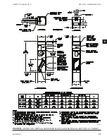
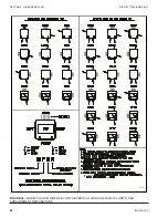
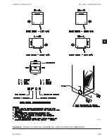
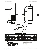
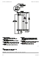
FIGURE 45 - 

ASSEMBLY INSTRUCTIONS RETURN PANEL WITH LATCHES, QUICK OPENING OR TAMPER 

PROOF, MODEL VHC/VHM/VHS HIGH RISE FCU

Содержание VHA

Страница 1: ...VERTICAL HI RISE FAN COILS SERIES B INSTALLATION OPERATION MAINTENANCE Supersedes ET115 24 NOM4 317 Form ET115 24 NOM4 819 MODELS VHC VHS VHM VERTICAL HI RISE VHA VHB TANDEM MASTER TANDEM SLAVE ...

Страница 2: ... document and any referenced materials This in dividual shall also be familiar with and comply with all applicable industry and governmental standards and regulations pertaining to the task in question SAFETY SYMBOLS The following symbols are used in this document to alert the reader to specific situations Indicates a possible hazardous situation which will result in death or serious injury if pro...

Страница 3: ... cautionary statements ELECTRICAL SHOCK HAZARDS All power must be disconnected prior to in stallation and servicing of this equipment More than one power source may be pres ent Disconnect all power sources to avoid electrocution or shock injuries MOVING PARTS HAZARDS Power must be disconnected from the motor and blower prior to opening access panels Motors can start automatically and more than one...

Страница 4: ...frigerants or lubricants Never pressurize any equipment beyond specified test pressures Always pressure test with some fluid or inert gas such as clear water or dry nitrogen on refrigera tion systems to avoid possible damage or injury in the event of a leak or component failure during testing The manufacturer assumes no respon sibility for personal injury or property damage resulting from improper...

Страница 5: ...ng Coil Hydronic Cooling Motor Deplugable Blower Assembly Slide Out Controls Refer to Appropriate Relay Board IOM if Present Optional Riser Chase Removable Typical Opening Knockout Supply Air Optional Risers Optional Blower Shield Access Door Control Enclosure Electric Heat Optional With Disconnect switch Incoming Power Optional Shipped Loose Room Thermostat Optional Shipped Loose Supply Air Grill...

Страница 6: ...side Air Damper 20 Motorized Outside Air Damper 20 Electrical Connections Shock Electrical Hazards 20 Thermostats 21 SECTION 2 START UP 23 General 23 Cooling Heating System 23 Air System Balancing 24 Water System Balancing 24 Controls Operation 24 Fan Coil EC Motor Control 25 G3 PWM Board 25 PWM Board Status LED 25 G3 PWM Status Descriptions 26 Adjusting EC Motor Speed 27 2 10 VDC Proportional Mot...

Страница 7: ...Heater Assembly 42 Electrical Wiring Controls 43 Valves Piping 43 Filters Throwaway 44 Drain 44 Optional Removable Drain Pan 44 Replacement Parts 44 SECTION 4 INSPECTION INSTALLATION START UP CHECKLIST 46 SECTION 5 TROUBLESHOOTING 48 SECTION 6 DIMENSIONAL DATA 51 Vertical Hi Rise Tandem Units VHA VHB Installation Instructions 75 Receipt Initial Installation 75 Temperature 79 ...

Страница 8: ...t CFM Constant Torque EC Motor Driver 35 FIGURE 26 Constant RPM EC Motor 1 4 HP Shown 36 FIGURE 27 Constant RPM EC Motor Driver 36 FIGURE 28 Constant RPM EC Driver EC Motor Enable Connector 37 FIGURE 29 Motor Power and Signal Connectors 39 FIGURE 30 Motor Blower Assembly 42 FIGURE 31 Electric Heat 43 FIGURE 32 Drain Pan Removal 44 FIGURE 33 Model VHM Vertical Concealed Master High Rise FCU 88 Cabi...

Страница 9: ...E 1 G3 Status LED Definition 25 TABLE 2 EC Motor Troubleshooting Guidelines 32 TABLE 3 Signal Connector 36 TABLE 4 Power Connector 36 TABLE 5 CON1 Power Input 36 TABLE 6 CON502 if present Programming Connector 36 TABLE 7 CON302 PWM Signal Input 36 TABLE 8 CON503 if present Motor Enable Input 37 TABLE 9 CON202 Feedback from EC Motor Hall Sensor 37 TABLE 10 CON201 Output Power to Motor 37 TABLE 11 E...

Страница 10: ...ENVIRO TEC 10 FORM ET115 24 NOM4 819 THIS PAGE INTENTIONALLY LEFT BLANK ...

Страница 11: ...ct for hidden damage At this time check to make sure that ship loose items such as grilles decorator panels and thermostats are accounted for Any hidden damage should be recorded and immediately reported to the carrier and a claim filed as before In the event a claim for shipping damage is filed the unit shipping package and all packing must be retained for physical inspection by the freight carri...

Страница 12: ...in and electri cal At this time it should be verified that the proper types of service are actually provided to the unit On those units requiring chilled water and or hot water the proper line size and water temperature should be available to the unit The electrical service to the unit should be compared to the unit nameplate to verify compatibility The routing and sizing of all piping and the typ...

Страница 13: ...PR 07 0115 3 4 NPSH Figure 1 FLEX HOSE CONNECTIONS LD13870 FIG 2C TOP VIEW TO REGULATE FLOW FIG 2C NOTE Valve package isolation valve shown typical for riser shut off valve FIG 2B TOP VIEW FIG 2A EXPLODED VIEW TO DESIRED FLOW MEMORY STOP ADJUSTED VALVE HANDLE WITH EAR BOTH SIDES MEMORY STOP EARS MEMORY STOP ADJUSTMENT RANGE MEMORY STOP STEP 1 SET VALVE TO DESIRED FLOW STEP 4 TIGHTEN SCREW AT TOP O...

Страница 14: ... time the joint is broken Later model units have a hose to coil joint with a black EDPM gasket Part No PH 05 0048 This gasket is re useable but may be replaced should it become damaged and no longer seal FACTORY INSTALLED RISERS Units provided with factory installed water and drain risers include fully insulated risers as specified per or der The flex hose and ball valve described above is assembl...

Страница 15: ...ed risers as specified per order which are shipped separately for installation on the job prior to receipt of the units The ball valve previously described is assembled to the riser and pressure tested at the factory The risers are pack aged as a kit for a specific location in the building and each kit is marked with that location by room number floor riser number or other identification as specif...

Страница 16: ...ermal expansion and con traction Units and risers are designed to accommodate a maximum of 3 1 1 2 up and 1 1 2 down total vertical movement To achieve this range of move ment the risers must be installed according to the conditions outlined below If the total combined riser expansion will exceed 3 additional expansion com pensation such as loops and expansion joints or alter nate riser anchoring ...

Страница 17: ...re blocking is the responsibility of the installer All penetrations for piping and risers should be sealed with materials and techniques suitable for all governing codes and ordi nances DUCTWORK CONNECTIONS All ductwork and or supply and return grills should be installed in accordance with the project plans and specifications If not included on the unit or furnished from the factory supply and ret...

Страница 18: ...hose using the hose clamp preciously removed After all the risers have been relocated inspect the cabinet insulation where the risers were removed and repair any insulation damage before starting the unit and cover unused openings DISCHARGE OPENING RECONFIGURATION Vertical Hi Rise and Tandem Master Tandem Slave units are furnished with discharge opening knock outs in all four sides and the top Sho...

Страница 19: ...d in the wall between the units Tandem Master Tandem Slave units are available with fire rated and non fire rated construction Non fire rated unit pairs may be installed as required to achieve the finished wall configuration desired Wall framing and drywall application should be accom plished as noted above Fire rated unit pairs are designed to be installed with the space between the units becomin...

Страница 20: ...h unit on a project may be different the installer must be familiar with the wiring diagram and nameplate on the unit BEFORE beginning any wiring Provide for adequately sized fuse circuit breaker or disconnect means as applicable to meet lo cal and national electrical codes All electrical connec tions should be checked for tightness prior to startup All components furnished for field installation ...

Страница 21: ...ould be removed from the unit and re installed on the thermostat mounting box or discarded as necessary Unit surface mounted thermostats are provided with a plug assembly for easy connection The plug is polarity specific and connects only in one direction Remote thermostats must be field wired to unit s connection points as indicated on the unit s wir ing diagram The fan motor s should never be co...

Страница 22: ...ENVIRO TEC 22 FORM ET115 24 NOM4 819 SECTION 1 RECEIPT INSTALLATION THIS PAGE INTENTIONALLY LEFT BLANK ...

Страница 23: ...ess panels or doors Except as required during start up and balancing operations no fan coil units should be oper ated without all the proper duct work attached supply and return grills in place and all access doors and pan els in place and secure A clean filter of the proper size and type must also be installed Failure to do so could result in damage to the equipment or building and fur nishings a...

Страница 24: ...and controls in the system The actual balancing technique may vary from one system to another After the proper system operation is established the appropriate system operating conditions such as vari ous water temperatures and flow rates should be re corded in a convenient place for future reference such as the inspection installation and start up check sheet see SECTION 4 INSPECTION INSTALLATION ...

Страница 25: ...ntrol EC motor speed between factory set minimum Min and maximum Max values For either control mode fan on off control is enabled via the G signal Tools Needed Digital multimeter capable of measuring 30 volts AC DC and duty cycle Insulated 1 8 flat bladed screwdriver Mini Hook Test Clips for multimeter optional Figure 12 G3 PWM BOARD PWM Board Status LED The G3 PWM Status LED refer to Figure 12 on...

Страница 26: ...pected mode replace the board Figure 13 PROGRAM MODE CONFIGURATION SWITCH 1 ON All power must be disconnected prior to installation and servicing this equipment More than one source of power may be present Disconnect all power sources to avoid electrocution or shock injuries Refer to lock out tag out procedures 1 Make sure there are no obstructions in the dis charge ductwork and or at the plenum o...

Страница 27: ... factory setting for minimum and maximum CFMs will invalidate the range for the Fan Calibration Curve as it will narrow the scale of the input signal 7 Follow instructions for adjusting EC motor speed using the G3 PWM board Separate instructions are provided for Three Speed adjustable and 2 10 VDC Proportional motor control modes LD19222 2 10V Manual Max High Medium Low Min 10 0 VDC 7 5 VDC 6 0 VD...

Страница 28: ...ressed once per programming session unless board times out Refer to Status LED Refer to voltmeter connected to TP1 and TP3 Using an insulated 1 8 flat bladed screwdriver adjust speed potentiometer to desired high speed airflow per Fan Calibra tion Curve on unit STORE Set switch 8 to Store ON wait one second then to Set OFF to save the value Figure 16 HIGH SPEED ADJUST 2 Medium speed Adjust Set Con...

Страница 29: ...C PROPORTIONAL MOTOR CONTROL Speed range adjustment for Proportional Control op eration Minimum Min and maximum Max speeds are programmed at the factory for optimum opera tion Changing factory Min or Max speed defaults will change the motor effective speed range and invalidate the voltage settings shown on the Fan Calibration Curve However the speed range may still be adjusted as long as the Min s...

Страница 30: ...step 3 Otherwise skip to step 5 3 Max Speed Adjust Set configuration switches to HI MAX SPEED balancing mode see Figure 21 on page 30 Switches to ON ON ON OFF OFF ON OFF OFF Set switch 1 to ON Program Set switch 2 to ON Analog Set switch 3 to ON Hi Max Set switches 4 and 5 to OFF Set switch 6 to ON 2 10 V Set switches 7 and 8 to OFF Refer to voltmeter connected to TP1 and TP3 Using an insulated 1 ...

Страница 31: ... OFF Refer to voltmeter connected to TP1 and TP3 Using an insulated 1 8 flat bladed screwdriver adjust speed potentiometer to desired Min speed airflow STORE Set switch 8 to Store ON wait one second then to Set OFF to save the value Figure 22 MIN SPEED ADJUST 5 Resume Normal 2 10 V DC Proportional Control Set configuration switches to OFF ON OFF OFF OFF ON OFF OFF for normal pro portional speed co...

Страница 32: ...nstant RPM EC motors will not rotate if they lose PWM signal while enabled Verify PWM signal at motor connector by connecting a multimeter set for duty cycle between pins 1P1 and 1C or between pins 2P1 and 2C The duty cycle represents the on time percentage signal sent to the motor this number will vary between the minimum and maximum duty cycle set by the factory See Figure 12 on page 25 for PWM ...

Страница 33: ...analog signal at Remote Control Input terminals Damaged or blocked blower Verify blower rotates freely Clear blockage Motor starts but stops Voltage or ground loss at motor driver Verify proper voltage and ground at motor driver power terminals Refer to Motor Driver Connections for the EC motor Motor overloaded blower binding Clear blockage Verify blower rotates freely with motor disconnected Moto...

Страница 34: ...connections Refer also to PWM Board Status LED on page 25 to verify board is in normal operating mode ESP external static pressure too high Verify dampers if present are not closed Verify there are no obstructions in the discharge ductwork and or at the plenum opening Verify filter is not dirty and does not obstruct airflow Motor driver failure Replace motor constant airflow or constant torque mot...

Страница 35: ...t EC driver Verify green wire has continuity to ground Unplug power wires from connections in electri cal enclosure Verify continuity of wires to motor driver then reconnect to same terminals Before reconnecting power to unit verify all harnesses are connected per diagram Use light force when inserting meter probe into plug Excess force will damage contacts EC MOTOR AND DRIVER There are two types ...

Страница 36: ...umper pin 1 to pin 2 for 120 VAC Line Input only 2 3 Chassis Ground 4 AC Line Line 1 5 AC Line Line 2 Neutral LD19310 LD19311 Constant RPM EC Motors Figure 26 CONSTANT RPM EC MOTOR 1 4 HP SHOWN Figure 27 CONSTANT RPM EC MOTOR DRIVER Table 5 CON1 POWER INPUT PIN DESCRIPTION 1 Ground 2 Neutral or Line 2 3 Line 1 Table 6 CON502 IF PRESENT PROGRAM MING CONNECTOR PIN DESCRIPTION 1 15V 2 Ground 3 TX 4 T...

Страница 37: ... 3 Hall W 4 Hall V 5 Hall U Table 10 CON201 OUTPUT POWER TO MOTOR PIN DESCRIPTION 1 W1 2 NC 3 V1 4 U1 Constant RPM EC Motor Driver Enable Jumper The ETI Constant RPM EC motor driver has a Mo tor Enable Input These drivers require a jumper across the Enable Connector to allow the unit to operate See Figure 10 for jumper location across pins 2 and 3 of the Enable Connector Figure 28 CONSTANT RPM EC ...

Страница 38: ...onnect them Loose wires in wiring harness With power removed from the unit verify that none of the wiring harnesses have loose wires Wiring harness is defective or damaged With power removed from the unit and the wiring harnesses disconnected verify continuity of harness from FCRB and from equipment ground to motor connector Replace wiring harness if suspect Refer to ECM Constant Torque Motor Spec...

Страница 39: ...ce all connections Ensure good connections are made Only very light force is required when inserting meter probe into plug Excess force will damage contacts ECM Constant Torque Motor Connections The ECM Constant Torque motor connector is located on the side of the motor It has two rows of terminals as shown in Figure 29 on page 39 The Power 4 pin connector plugs into the top row The Signal 5 pin c...

Страница 40: ...N MOTOR MED Blue High Static Option High Speed 5 TO FAN MOTOR HIGH ECM Constant Torque Motor Specifications Table 15 ECM CONSTANT TORQUE MOTOR PART NUMBERS TYPE POWER PART VOLTAGE ECM 3 SPD 1 3 HP PM 02 0425 277 ECM 3 SPD 1 3 HP PM 02 0426 115 ECM 3 SPD 1 3 HP PM 02 0427 208 230 Table 16 MOTOR SIGNAL TAP SPECIFICATIONS Min On voltage greater than 12VAC or 15VDC Maximum voltage 33VAC or 23VDC Min O...

Страница 41: ...ENVIRO TEC 41 SECTION 2 START UP FORM ET115 24 NOM4 819 THIS PAGE INTENTIONALLY LEFT BLANK ...

Страница 42: ...ed to accumulate on the blower wheel or housing This can result in an un balanced blower wheel condition that can damage a blower wheel or motor The wheel and housing may be cleaned periodically using a vacuum cleaner and a brush taking care not to dislodge the factory balancing weights on the blower wheel blades SHIELD BLOWER OPTIONAL TYP 4 PLCS TYP 2 PLCS Figure 30 MOTOR BLOWER ASSEMBLY COIL Coi...

Страница 43: ...ation Some components may experi ence erratic operation or failure due to age Wall ther mostats may also become clogged with dust and lint and should be periodically inspected and cleaned to provide reliable operation When replacing any components such as fuses contactors or relays use only the exact type size and voltage component as furnished from the factory Any deviation without factory author...

Страница 44: ...eaning see Figure 32 on page 44 To remove the pan disconnect the drain p trap by loosen ing the hose clamp under the pan Remove the retainer plate at the front of the pan and slide the pan out of its track Clean or service pan as appropriate Rein stall pan in reverse sequence Retainer plate must be installed for proper operation Figure 32 DRAIN PAN REMOVAL REPLACEMENT PARTS Factory replacement par...

Страница 45: ...ENVIRO TEC 45 SECTION 3 NORMAL OPERATION PERIODIC MAINTENANCE FORM ET115 24 NOM4 819 THIS PAGE INTENTIONALLY LEFT BLANK ...

Страница 46: ... _________ All Shipping Screws Braces Removed __________ _________ COOLING HEATING CONNECTIONS Protect Valve Package Components From Heat __________ _________ Mount Valve Packages __________ _________ Connect Field Piping To Unit __________ _________ Pressure Test All Piping For Leaks __________ _________ Install Drain Line Traps As Required __________ _________ Insulate All Piping As Required ___...

Страница 47: ...cord All Final Settings For Future Use __________ _________ Check Piping Ductwork For Vibration __________ _________ Check All Dampers For Proper Operation __________ _________ Verify Proper Cooling Operation __________ _________ Verify Proper Heating Operation __________ _________ Reinstall All Covers Access Panels __________ _________ SERVICE INTERVALS record dates service performed Filters ____...

Страница 48: ...iring of all incoming power devices and remote mounted controls UNIT BLOWS MAIN UNIT OR FAN MOTOR FUSE WHEN POWER IS APPLIED TO UNIT Defective or improperly wired component Using a battery powered continuity tester check for shorted or grounded components starting at incoming power Note position of all controls during various component checks Caution some voltages have isolated common which may no...

Страница 49: ... wheel on motor shaft or replace as required FAN RUNS BUT AIR DELIVERY IS LOW Incorrect fan speed has been selected Reselect proper fan speed as required Dirty air filter Replace air filter Dirty coil Clean coil Obstruction in ductwork Check for improperly positioned balancing or fire dampers Check for fallen duct liner Repair as required Actual E S P higher than design Check installation for prop...

Страница 50: ...heater does not operate after sufficient time for limit switch to cool disconnect power and check continuity across primary high limit switch Replace if defective Tripped secondary high limit switch Secondary high limit switches are designed to trip only during extreme failure conditions Contact factory before attempting any corrective action Defective thermostat Momentarily jumper thermostat cont...

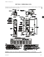
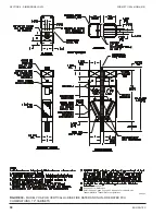
Страница 51: ...ODEL VHM VERTICAL CONCEALED MASTER HIGH RISE FCU 88 CABINET 74 80080 SECTION 6 DIMENSIONAL DATA The drawings in this section are for reference only and should not be used for construction purposes Reference submittal documents for most current version ...

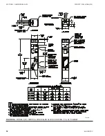
Страница 52: ...ENVIRO TEC 52 FORM ET115 24 NOM4 819 SECTION 6 Dimensional Data Figure 34 MODEL VHS VERTICAL CONCEALED SLAVE HIGH RISE FCU 88 CABINET 74 80081 ...

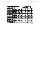
Страница 53: ...ENVIRO TEC 53 SECTION 6 Dimensional Data FORM ET115 24 NOM4 819 6 Figure 35 MODEL VHA VHB VERTICAL HI RISE TANDEM FIRE RATED AND NON FIRE RATED FCU COMBINATIONS 88 CABINETS 74 80083 ...

Страница 54: ...ENVIRO TEC 54 FORM ET115 24 NOM4 819 SECTION 6 Dimensional Data 74 80083 ...

Страница 55: ...ENVIRO TEC 55 SECTION 6 Dimensional Data FORM ET115 24 NOM4 819 6 Figure 36 MODEL VH VERTICAL CONCEALED HIGH RISE FAN COIL UNIT WITH 79 CABINET VH 031 ...

Страница 56: ...ENVIRO TEC 56 FORM ET115 24 NOM4 819 SECTION 6 Dimensional Data Figure 37 MODEL VHM VERTICAL CONCEALED MASTER HIGH RISE FAN COIL UNIT WITH 79 CABINET VH 032 ...

Страница 57: ...ENVIRO TEC 57 SECTION 6 Dimensional Data FORM ET115 24 NOM4 819 6 Figure 38 MODEL VHS VERTICAL CONCEALED SLAVE HIGH RISE FAN COIL UNIT WITH 79 CABINET VH 033 ...

Страница 58: ...al Data Figure 39 MODEL VHA VHB VERTICAL HI RISE FIRE RATED AND NON FIRE RATED FCU COMBINATIONS 79 CABINETS VH 006 1 on page 75 See page 67 for dimensions Refer to page 61 page 62 page 63 page 64 for vertical Hi rise Tandem Master Tandem Slave configurations ...

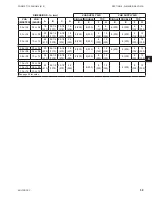
Страница 59: ... 1 2 470 18 457 8 203 8 203 6 152 12 305 8 203 8 203 6 152 12 305 03 or 04 10 or 12 24 610 54 1 4 1378 22 1 2 572 22 559 8 203 8 203 8 203 12 305 8 203 8 203 12 305 06 or 08 03 or 04 20 508 46 1 4 1175 18 1 2 470 18 457 8 203 8 203 6 152 12 305 8 203 8 203 6 152 12 305 06 or 08 06 or 08 06 or 08 10 or 12 24 610 54 1 4 1378 22 1 2 572 22 559 8 203 8 203 8 203 12 305 8 203 8 203 12 305 10 or 12 03 o...

Страница 60: ...ENVIRO TEC 60 FORM ET115 24 NOM4 819 SECTION 6 Dimensional Data VHC VHS VHM VHA VHB VHA VHB Figure 40 MODEL VH VERTICAL HIGH RISE COIL UNIT ALUMINUM DISCHARGE GRILLE 74 80020 ...

Страница 61: ...NOM4 819 6 Figure 41 MODEL VHC VHM VHA VERTICAL HIGH RISE FAN COIL UNIT ARRANGEMENT DESIGNATIONS MODEL VHC UNITS SHOWN ABOVE WITH OPTIONAL RISER CHASE RISER CHASE NOT AVAILABLE ON VHM UNITS VHA UNITS MUST BE MATED TO VHB UNITS VH 010 SEE PAGE 63 FOR DETAILS ...

Страница 62: ...EC 62 FORM ET115 24 NOM4 819 SECTION 6 Dimensional Data VHC AND VHS VHB VHA Figure 42 MODEL VHC W O RISERS VHS VHB VERTICAL HIGH RISE FAN COIL UNITS UNIT ARRANGEMENT DESIGNATIONS VH 011 SEE PAGE 63 FOR DETAILS ...

Страница 63: ...ENVIRO TEC 63 SECTION 6 Dimensional Data FORM ET115 24 NOM4 819 6 VHC VH VH 018 Figure 43 MODEL VH VERTICAL HIGH RISE COIL UNIT OUTSIDE INLET DIMENSIONS ...

Страница 64: ...l Data Figure 44 MODEL VHM VHA VHC TANDEM MASTER TANDEM SLAVE UNIT CONFIGURATION FAN COIL UNIT TANDEM MASTER TANDEM SLAVE INSTALLATION INSTRUCTIONS ON PAGES TANDEM MASTER TANDEM SLAVE FIRE RATED TANDEM MASTER TANDEM SLAVE NON FIRE RATED VH 043 page 75 page 77 ...

Страница 65: ...ENVIRO TEC 65 SECTION 6 Dimensional Data FORM ET115 24 NOM4 819 6 VH 106 Figure 45 ASSEMBLY INSTRUCTIONS RETURN PANEL WITH LATCHES QUICK OPENING OR TAMPER PROOF MODEL VHC VHM VHS HIGH RISE FCU ...

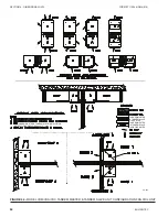
Страница 66: ...ENVIRO TEC 66 FORM ET115 24 NOM4 819 SECTION 6 Dimensional Data VHS VHS VH VH VHS Figure 46 PREPARATION INSTRUCTIONS FOR MODEL VHC VHM VERTICAL HIGH RISE FCU SHIP LOOSE RISER ASSEMBLIES ...

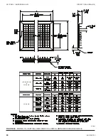
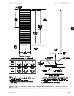
Страница 67: ...ENVIRO TEC 67 SECTION 6 Dimensional Data FORM ET115 24 NOM4 819 6 VH 013 Figure 47 FULL LOUVERED ALUMINUM RETURN AIR WALL PANEL MODEL VH VERTICAL HIGH RISE FAN COIL UNIT ...

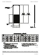
Страница 68: ...ENVIRO TEC 68 FORM ET115 24 NOM4 819 SECTION 6 Dimensional Data Figure 48 MODEL VH VERTICAL HIGH RISE FAN COIL UNIT STANDARD SURFACE MOUNT WALL PANEL 74 80084 ...

Страница 69: ...9 SECTION 6 Dimensional Data FORM ET115 24 NOM4 819 6 assembly instructions on in Tandem Master Tandem Slave pairs VH 014 Figure 49 RECESSED WALL PANEL MODEL VH VERTICAL HIGH RISE FAN COIL UNIT page 65 for details ...

Страница 70: ...5 24 NOM4 819 SECTION 6 Dimensional Data assembly instructions on page for details in Tandem Master Tandem Slave pairs VH 047 Figure 50 MODEL VH VERTICAL HIGH RISE FAN COIL UNIT STANDARD RETURN WALL PANEL WITH ADA THERMOSTAT ...

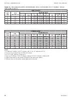
Страница 71: ...R DATA W IN H IN Pv in W G Pt in W G Ps IN W G NC THROW FT DROP FT 03 375 16 8 0 006 0 0170 0 0110 20 11 24 10 04 450 16 8 0 008 0 0230 0 0150 20 11 27 10 5 06 616 18 12 0 003 0 0072 0 0042 20 10 35 11 5 08 860 18 12 0 006 0 0170 0 0110 20 12 37 12 10 966 22 14 0 006 0 0170 0 0110 20 13 42 12 12 1350 22 14 0 008 0 0230 0 0150 20 14 45 14 NOTES 1 NC data is at 0 deflection For 22 5 deflection add 1...

Страница 72: ...N W G NC THROW FT DROP FT 03 375 16 8 0 003 0 0072 0 0042 20 8 25 9 04 450 16 8 0 005 0 0160 0 0110 20 9 25 10 06 616 18 8 0 007 0 0180 0 0110 20 13 30 10 08 860 18 8 0 015 0 0380 0 0230 21 18 39 11 10 966 22 8 0 015 0 0380 0 0230 20 17 42 12 5 12 1350 22 8 0 019 0 0560 0 0370 21 21 45 14 NOTES 1 NC data is at 0 deflection For 22 5 deflection add 1 NC For 45 deflection add 7 NC 2 Throws are for ve...

Страница 73: ...ENVIRO TEC 73 SECTION 6 Dimensional Data FORM ET115 24 NOM4 819 6 Figure 51 SUGGESTED RISER FLOOR OPENINGS VHC VHM VH 109 ...

Страница 74: ...ENVIRO TEC 74 FORM ET115 24 NOM4 819 SECTION 6 Dimensional Data Figure 52 RISER TERMINOLOGY MODEL VHC VHM VHA UNITS VH 110 ...

Страница 75: ...n ap plicable attach studs of the wall to the unit spacer plate with sheet metal screws spaced nominally 12 O C When built of gypsum construction the following minimum requirements must be met a Studs Wood or steel studs nominal 3 1 2 thick spaced maximum 24 O C b Gypsum Board Minimum 5 8 Type X Gypsum board with a minimum of one layer Gypsum board must be installed on each side of the wall assemb...

Страница 76: ...t top front and two top sides as shown in Figure 54 on page 76 b Attach steel track using sheet metal screws spaced 12 O C c Install identical steel track to the ceiling or floor assembly using appropriate anchors Friction fit minimum 25 GA nominal 3 1 2 steel studs into the top and bottom track and secure with pan head screws d Install one stud at each corner of the fan coil unit e Install gypsum...

Страница 77: ...OF UNIT TO CEILING 4 CORNERS 9 INSTALL GYPSUM BOARD TO WALLS SHEET 2 OF 2 5 INSTALL WALL STUD INTO RECESS FORMED BY CONNECTOR PLATE SEE DETAIL A ABOVE MAY VARY RISER LOCATION WALL STUDS 5 8 TYPE X GYPSUM BOARD FIELD SUPPLIED 5 8 TYPE X GYPSUM BOARD FACTORY SUPPLIED 3 5 8 25 GA STEEL STUD 24 O C TYP 6 X 1 2 DRYWALL SCREWS CAUTION AVOID PLACING SCREW WHERE THEY MAY PENETRATE THE RISER COIL PIPING OR...

Страница 78: ...ENVIRO TEC 78 FORM ET115 24 NOM4 819 SECTION 6 Dimensional Data NOTES ...

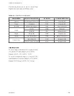
Страница 79: ...tiply by 5 9 or 0 5556 Example 10 0 F range x 0 5556 5 6 C range Table 20 SI METRIC CONVERSION MEASUREMENT MULTIPLY ENGLISH UNIT BY FACTOR TO OBTAIN METRIC UNIT Capacity Tons Refrigerant Effect ton 3 516 Kilowatts kW Power Horsepower 0 7457 Kilowatts kW Flow Rate Gallons Minute gpm 0 0631 Liters Second l s Length Feet ft 0 3048 Meters m Inches in 25 4 Millimeters mm Weight Pounds lbs 0 4538 Kilogr...

Страница 80: ... Controls in the United States of America and other countries Other trademarks used herein may be trademarks or registered trademarks of other companies Catalog ET115 24 NOM4 819 Supersedes ET115 24 NOM4 317 2019 Johnson Controls www enviro tec com ...

Отзывы: