17
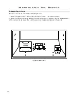
Figure 20: Valve Cover.
Maintenance And Service
R
emoVing
V
aLVe
c
oVeR
:
The valve cover can be removed to access the gas valve.
1. Remove the glass door as shown in
m
aIntenance
anD
s
erVIce
- g
lass
D
oor
r
emoVal
.
2. Remove the liners and burner. Refer to
s
econDary
I
nstallatIon
- F
Irebox
l
Iner
anD
b
urner
r
emoVal
.
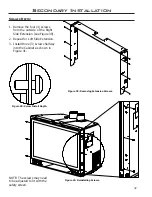
3. Then remove the six screws that hold the valve cover in place (pointed out in Figure 10).
VALVE
COVER
Содержание E30GI
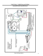
Страница 26: ...26 Initial Installation QUALIFIED INSTALLERS ONLY 5 of 10 Figure 30 Wiring Schematic ...
Страница 44: ...44 Parts Diagram Components 1 15 2 13 3 4 16 6 7 12 5 14 19 8 20 18 17 11 10 9 ...
Страница 45: ...45 Parts Diagram Options 22 26 23 24 27 25 28 21 29 ...
Страница 46: ...46 NOTES ...

