10
Operating Instructions
Operating Instructions
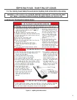
ATTENTION!
- TURN “OFF” THE MAIN GAS SUPPLY OF THE APPLIANCE DURING INSTALLATION OR
MAINTENANCE OF THE RECEIVER.
- PLACE THE RECEIVER’S 3 POSITION SLIDER SWITCH IN THE “OFF” POSITION DURING
INSTALLATION OR MAINTENANCE.
- TURN “OFF” MAIN GAS SUPPLY TO THE APPLIANCE PRIOR TO REMOVING OR REINSERTING
THE BATTERIES IN THE RECEIVER.
- DURING APPLIANCE INSTALLATION/MAINTENANCE OR IN CASE OF REMOTE CONTROL
MALFUNCTION TURN OFF THE FAN CONTROL MODULE USING THE “ON/OFF” MAIN POWER
SWITCH ON THE FRONT PANEL OF THE FCM.
t
echnicaL
D
ata
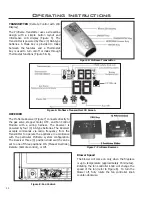
Transmitter (Remote Control):
Supply voltage 4.5 V (three 1.5 V AAA batteries)
Ambient temperature ratings 0 - 50 °C (32 - 122 °F)
Receiver:
Supply voltage 6.0 V (four 1.5 V AA batteries)
s
ystem
D
escRiption
:
The Proflame Remote Control System consists of two elements:
1. Proflame Transmitter.
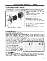
2. Proflame Receiver and a wiring harness to connect the Receiver to the gas valve and stepper motor.
s
witching
to
c
ontinuous
p
iLot
m
oDe
:
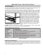
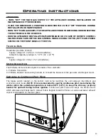
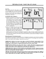
The toggle switch located on the bottom right corner switches the unit between intermittent and
continuous pilot modes.
NOTE: It is recommended to use the continuous pilot mode during the
winter when the outside temperature is below 50
°F (10°C) to keep the chimney properly
heated for updraft during burner ignition.
Continuous pilot mode also keeps the firebox warm
which eliminates both heat loss to cold air that is trapped inside the firebox as well as excessive exhaust
vapour condensation on the door glass.
Содержание E30GI
Страница 26: ...26 Initial Installation QUALIFIED INSTALLERS ONLY 5 of 10 Figure 30 Wiring Schematic ...
Страница 44: ...44 Parts Diagram Components 1 15 2 13 3 4 16 6 7 12 5 14 19 8 20 18 17 11 10 9 ...
Страница 45: ...45 Parts Diagram Options 22 26 23 24 27 25 28 21 29 ...
Страница 46: ...46 NOTES ...


