background image

Secondary Installation

s

uRRounD

 p

aneL

 i

nstaLLation

WARNING: 

The surround becomes hot when the unit is operating; ensure that the unit is turned off, and that 

it has cooled to room temperature before beginning this installation. 

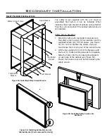
Height

Width

3-Sided Surround

25” (635 mm)

39 

7

/

8

” (1013 mm)

4-Sided Surround

31 

1

/

2

” (800 mm) 39 

7

/

8

” (1013 mm)

Table 7: Surround Dimensions.

Please check components supplied with this kit. If components are missing or have been damaged, contact your 

dealer, distributor or courier company before starting this installation.

IMPORTANT:

 The panel must not seal ventilation openings in the fireplace.

INSTALLATION (3 and 4 sided Surrounds): 

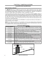
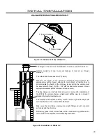
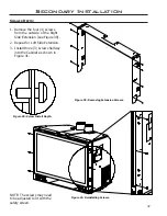
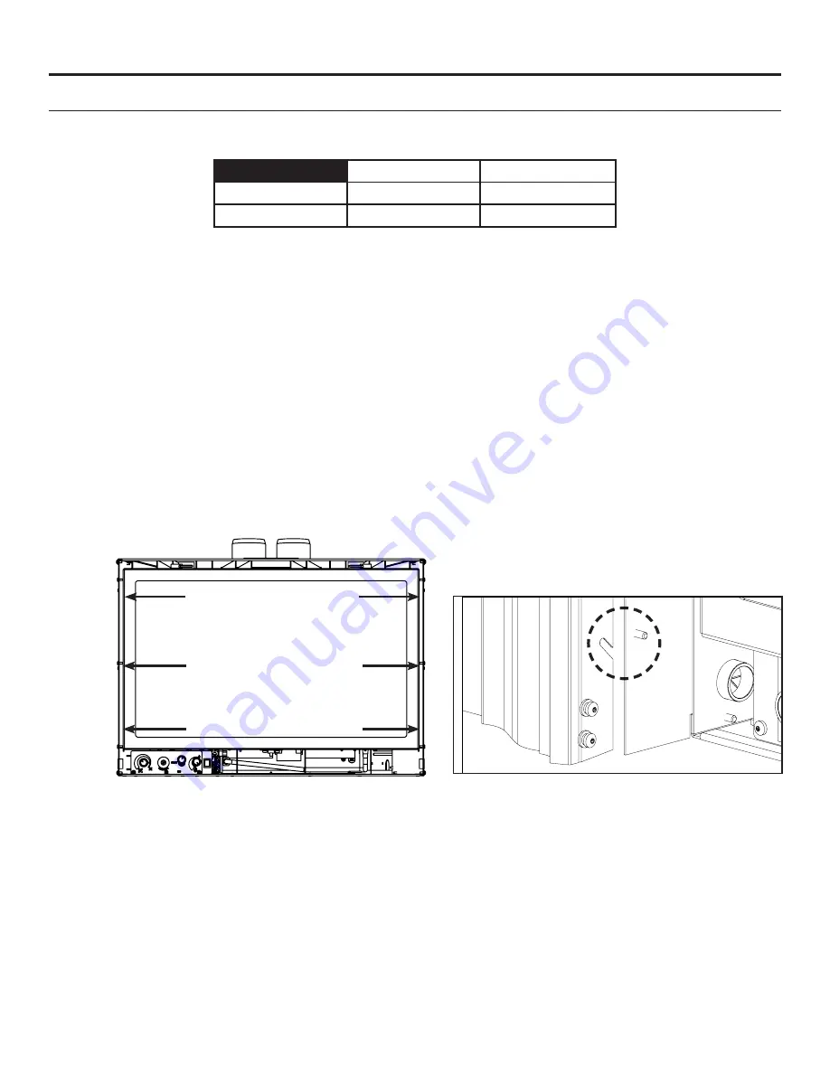
Lift the face upright in front of the fireplace with the six hooks pointing towards the fireplace. Slide the hooks 

over  their  corresponding  screws  (see  Figures  52  &  53).  Ensure  the  hooks  are  secure  before  releasing  the 

surround. The surround should be wiped with a damp cloth periodically. Screws can be tightened for a more 

permanent install.

REMOVAL: 

Lift the surround straight up in order to unhook the notch on the hooks from the screws. Pull the surround away 

from the fireplace. Place the surround where it will not be damaged.

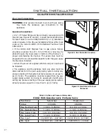
Figure 52: Screw Locations.

Figure 53: Screw and Hook Close-Up.

BURNER SWITCH WIRING INSTALLATION:

The burner switch supplied with the surround comes pre-installed and wired. The wiring from the burner switch 

simply needs to be connected to the wiring on the E30 unit. 
The wiring harness for the burner switch has one (1) blue wire, one (1) grey wire and two (2) purple wires.
The blue wire connects to the blue wire on the E30 unit, the grey wire connects to the grey wire on the E30 unit, 

and the purple wires are used to connect an optional thermostat. 

CLEANING:

Painted surfaces should be periodically wiped with a damp cloth. 

Never clean the face when it is hot.

Access Panel
removed for 
clarity.

35

B

Содержание E30GI

Страница 1: ...INSERT Glass Burner Proflame IPI Valve OWNER S MANUAL Version Française www enviro com fr html Report 268 S 23 5 WARNING If the information in this manual is not followed exactly a fire or explosion may result causing property damage personal injury or loss of life Installation and service must be performed by a qualified installer service agency or the gas supplier ...

Страница 2: ...l your gas supplier from a neighbor s phone Follow the gas supplier s instructions If you cannot reach your gas supplier call the fire department Installation and service must be performed by a qualified installer service agency or the gas supplier Massachusetts installations Warning This product must be installed by a licensed plumber or gas fitter when installed within the Commonwealth of Massac...

Страница 3: ...Code ANSI Z223 1 2 USA To prevent injury do not allow anyone who is unfamiliar with the stove to operate it To prevent injury if the pilot or pilot and burners have gone out on their own open the glass door and wait 5 minutes to air out before attempting to re light the stove Always keep the area around these appliances clear of combustible material gasoline and other flammable liquids and vapours...

Страница 4: ...ving Valve Cover 17 Fuel Conversion 18 Initial Installation 20 Clearances to Combustibles 20 Minimum Fireplace Size 20 Direct Vent Model 20 Venting Fireplace Inserts 21 Direct Vent Vertical Vent Termination 23 Installing the Unit 24 Zero Clearance Fireplace Installation 25 Electrical Requirements 26 Gas Line Connection 27 Adjusting The Pilot Flame 29 Secondary Installation 30 Optional Base Shelf R...

Страница 5: ...TING METHOD FOR MEASURING ANNUAL FIREPLACE EFFICIENCY This ENVIRO E30GI Fireplace Insert Has been certified for use with either natural or propane gases See rating label Is not for use with solid fuels Is approved for bedroom or bed sitting room IN CANADA must be installed with a permanent wall thermostat for bedroom installations Consult the authority having local jurisdiction in your area IN USA...

Страница 6: ... 62 1 30 3 07 17 71 19 60 15 67 LEFT RIGHT FRONT Install Depth If the available depth of install is less than the 17 71 shown above the stove depth can be reduced to 15 67 by removing the cabinet extension brackets however doing so will cause the safety screen to protroud past the front of the surround panel If the reduced install depth is required the extension brackets must be removed Refer to S...

Страница 7: ...ontemporary Surround Extruded Surround Height 25 635mm 25 635mm 25 635mm Width 39 7 8 1013 mm 39 7 8 1013 mm 39 7 8 1013 mm Trimmable Surround Height Width 38 965mm 46 1168mm Base Shelf Base Shelf Riser Height 1 41mm 2 54mm Width 41 5 8 1057mm 40 1 4 1022mm Depth Bottom 4 112mm Top 3 13 16 97mm 3 11 16 94mm 39 5 8 41 5 8 25 27 3 8 ...

Страница 8: ...ance and to replace any part of the control system and any gas control which has been under water OPERATING INSTRUCTIONS 1 STOP Read the safety information above on this label 2 Read the owner s manual including the section on Remote Control operation 3 Set the thermostat to the lowest setting 4 Turn off all electric power to the appliance 5 Do not attempt to light the pilot by hand 6 Wait five 5 ...

Страница 9: ...mount of air coming into the fireplace to be adjusted in order to accommodate different climates and venting arrangements Start the pilot and then the burner Make sure the pilot flame is burning normally and none of the burner ports are plugged Let the fireplace burn for roughly fifteen 15 minutes and then examine the flames The ideal flame will be blue at the base and light orange above The flame...

Страница 10: ...nt temperature ratings 0 50 C 32 122 F Receiver Supply voltage 6 0 V four 1 5 V AA batteries System Description The Proflame Remote Control System consists of two elements 1 Proflame Transmitter 2 Proflame Receiver and a wiring harness to connect the Receiver to the gas valve and stepper motor Switching to Continuous Pilot Mode The toggle switch located on the bottom right corner switches the unit...

Страница 11: ... 4 AA type batteries The Receiver accepts commands via radio frequency from the Transmitter to operate the appliance in accordance with the particular Proflame system configuration The Receiver three 3 position slider switch can be set to one of three positions ON Manual Override Remote Remote control or Off Figure 5 Proflame Transmitter Figure 6 Proflame Transmitter LCD Screen Figure 7 Proflame R...

Страница 12: ...ature display see Figure 10 Turn on the Appliance Press the ON OFF Key on the Transmitter The Transmitter display will show all active Icons on the screen A single beep from the Receiver will confirm reception of the command and will commence to first ignite the pilot light followed by the main burner This should take about 10 seconds to complete Figure 10 Remote Control Display in Farenheit and C...

Страница 13: ...emperature and the actual room temperatures As the room temperature gets closer to the set point the Smart Function will modulate the flame down To activate this function press the Thermostat Key Figure 6 until the word SMART appears to the right of the temperature bulb graphic Figure 12 To adjust the set temperature press the Up or Down Arrow Keys until the desired set temperature is displayed on...

Страница 14: ...placed the beep will be emitted from the Receiver when the ON OFF Key is pressed See Initializing The System For The First Time Manual Bypass Of The Remote System If the batteries of the Receiver or Transmitter are low or depleted the appliance can be turned on manually by sliding the three position slider switch on the Receiver to the ON position This will bypass the remote control feature of the...

Страница 15: ...ces Depending on the amount of use the glass should require cleaning no more than two or three times a season Do not clean the glass when it is hot Cleaning The Firebox Remove the glass material Vacuum the bottom of the firebox thoroughly At this time inspect the burner tube for cracking or severe warping If a problem is suspected contact the dealer Replacing The Glass The glass in the fireplace i...

Страница 16: ...r operate the fireplace with the glass removed CAUTION GLASS MAY SEPARATE FROM DOOR Figure 18 Door Release Figure 19 Door Removal Remove the glass door by placing the hooked end of the door release tool in the hole on the door latch mechanism see Figure 18 and pulling the latch out then up When the two 2 latches have been released tilt the bottom of the door forward and then lift up to unhook the ...

Страница 17: ...d to access the gas valve 1 Remove the glass door as shown in Maintenance and Service Glass Door Removal 2 Remove the liners and burner Refer to Secondary Installation Firebox Liner and Burner Removal 3 Then remove the six screws that hold the valve cover in place pointed out in Figure 10 VALVE COVER ...

Страница 18: ...as already been connected to a gas supply shut off the gas supply to the unit CAUTION The gas supply must be shut off prior to disconnecting the electrical power and before proceeding with the conversion 3 If the unit has been run shut off and allow cooling to room temperature 4 Remove the door as shown in the Maintenance and Service Glass Door Removal 5 Carefully remove the firebox liners 6 Remov...

Страница 19: ...p is similar to what is shown in Figure 21 11 Reconnect the electrical power to the unit 12 Refer to the Operating Instructions to light the unit and verify proper burner ignition and operation and proper flame appearance 13 MAKE SURE that the conversion label is installed on or close to the rating label to signify that the unit has been converted to a different fuel type Figure 21 Ignitor assembl...

Страница 20: ...k Height Depth Fireplace Dimensions 28 711 mm 18 1 2 470 mm 20 508 mm 14 1 4 368 mm NOTE Space must be provided for gas line on left side of unit for servicing purposes 36 914 mm minimum to bottom of unit 12 305mm Mantel 30 762 mm minimum to bottom of unit Combustible Facing Direct Vent WARNING This appliance has been designed to draw room air for proper heat circulation from the sides and bottom ...

Страница 21: ...d in accordance with the National Provincial State and local building codes and has been constructed of non combustible materials Before starting refer to Initial Installation Preparing Your E30GI For Installation Please reference the information in Table 4 and Figures 23 and 25 An approved chimney liner and rain cap must be used A throat connector or flashing must be installed to ensure a tight s...

Страница 22: ...eight of the chimney Every joint in the venting must be secured with three 3 8 x 3 8 HWH sheet metal screws and an appropriate sealant either silicone or stove cement The flue damper can be fully blocked open or removed for installation of the E30GI the smoke shelves shields and baffles may be removed if attached by mechanical fasteners The fireplace and fireplace chimney must be clean in good wor...

Страница 23: ...med down and folded over 5 Apply a bead of stove cement sealant to the top section of the Ø3 76mm exhaust vent collar plate Slide the Ø3 76mm flex vent over the flue collar and secure with three 3 sheet metal screws evenly spaced 6 Place a bead of high temperature silicone on the intake collar of the fireplace slide the Ø3 76mm flex intake liner over the collar secure the flex liner with three 3 s...

Страница 24: ...e stove above the door opening see Figure 27 Slide the collar plate backwards Properly secure the vent collar plate to the flexible vent pipe liner s previously installed in the chimney Be careful not to over stretch the liner s 6 Place the unit part way into the fireplace Connect the gas line to the NPT pipe nipple at the lower left rear of the unit using locally approved methods see Initial Inst...

Страница 25: ...ture rating of 105 C Electrical Requirements Zero Clearance ZC Fireplace Installation The metal floor of the ZC solid fuel firebox can be removed to allow the installation of the insert THE CLEARANCE TO COMBUSTIBLE MATERIAL UNDER THE INSERT IS 2 1 4 57 2 mm YOU MUST USE THE LEVELING LEGS TO RAISE THE INSERT A MINIMUM OF 2 1 4 57 2 mm IF THE UNIT IS TO BE INSTALLED ON COMBUSTIBLE MATERIAL The optio...

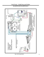
Страница 26: ...26 Initial Installation QUALIFIED INSTALLERS ONLY 5 of 10 Figure 30 Wiring Schematic ...

Страница 27: ...n installed A shut off valve is not supplied with this unit but one should be installed The appliance and its appliance main gas valve must be disconnected from the gas supply piping system during any pressure testing of that system at test pressures in excess psi 3 5 kPa The appliance must be isolated from the gas supply piping system by closing its equipment shutoff valve during any pressure tes...

Страница 28: ... taps 3 Check pressures using a manometer 4 When finished remove hose and tighten set screw Always check for gas leaks with a soap and water solution after completing the required pressure test NEVER USE AN OPEN FLAME FOR LEAK TESTING 28 Initial Installation QUALIFIED INSTALLERS ONLY 1 2 3 Item Number Description 1 Pilot Adjustment Screw 2 Inlet Pressure Test Point 3 Outlet Pressure Test Point Fig...

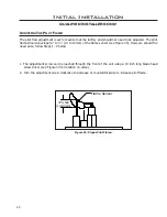
Страница 29: ...4 However should the need arise follow Steps 1 2 below Figure 34 Proper Pilot Flame Initial Installation QUALIFIED INSTALLERS ONLY 1 The adjustment screw can be reached through the front of the unit using a 10 inch long blade head screw driver see Figure 33 for location on valve 2 Turn the adjustment screw clockwise to decrease or counterclockwise to increase pilot flame 375 500 10 13mm Flame Sens...

Страница 30: ...mbly in front of the unit flush with the bottom of the unit 6 Install surround if required Secondary Installation Optional Base Shelf Riser The E30GI Base Shelf 1 41 mm high and Base Shelf Riser 2 54 mm high are components that can be combined to create a riser with an overall height of 23 16 55 mm This shelf can be installed with or without the riser and can be used when the hearth in front of th...

Страница 31: ...If the reduced install depth is required the top and side extensions will need to be removed and the hardware re located as outlined in steps 1 5 below REMOVAL 1 Using a T20 screwdriver remove the four 4 scrrews that secure the Top Extension to the Cabinet see Figure 38 2 Remove the four 4 screws on each Side Extension see Figure 38 Side Cabinet Extensions A Figure 38 Removing Extension Screws Ste...

Страница 32: ...crews NOTE The screws may need to be adjusted to fit with the safety screen 1 Remove the four 4 screws from the outside of the Right Side Extension see Figure 39 2 Repeat for Left Side Extension 3 Install three 3 screws halfway into the Cabinet as shown in Figure 41 32 Figure 40 Screw Install Depth ...

Страница 33: ...rom direct measurements of offset and remove any sharp edges 5 The panel can be touched up with a high temperature metallic black paint available from your dealer REDUCED DEPTH INSTALLATION 1 Install the two Trimmable Panel brackets onto the E30 unit using a T 20 Torx screwdriver See Figures 42 and 43 for the screw installation locations There are three sets of hole patterns on the brackets depend...

Страница 34: ...asurements of offset and remove any sharp edges 5 The panel can be touched up with a high temperature metallic black paint available from your dealer REGULAR DEPTH INSTALLATION 1 Install the two Trimmable Panel brackets onto the E30 unit using a T 20 Torx screwdriver See Figures 46 and 47 for the screw installation locations There are three sets of hole patterns on the brackets depending on which ...

Страница 35: ...are secure before releasing the surround The surround should be wiped with a damp cloth periodically Screws can be tightened for a more permanent install REMOVAL Lift the surround straight up in order to unhook the notch on the hooks from the screws Pull the surround away from the fireplace Place the surround where it will not be damaged Figure 52 Screw Locations Figure 53 Screw and Hook Close Up ...

Страница 36: ...nd panel if the cabinet extensions are still installed Safety Screen Assembly 1 Attach the left right top bottom brackets onto the safety screen using a T20 screwdriver and the supplied sixteen 16 8 T20 screws see Figure 54 Do not over tighten the screws doing so could cause them to strip out of the screen frame 2 Lift the face upright in front of the fireplace with the four 4 hooks pointing towar...

Страница 37: ...he liners and the burner tray NOTE Follow the steps in the reverse order for reassembly Secondary Installation Figure 58 Remove the clips which secure the side panels and then pull the bottom of the panels towards the center of the firebox Figure 59 Remove the rear brick panel by pulling it forward off the ledge Figure 56 Remove the six T20 screws and then remove the bottom panel by lifting up Fig...

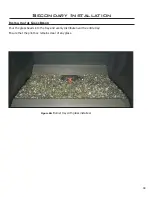
Страница 38: ... Installation Installing the Glass Beads Pour the glass beads into the tray and evenly distribute over the entire tray Ensure that the pilot box remains clear of any glass Figure 60 Burner tray with glass installed ...

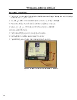
Страница 39: ...k one 1 time in intervals 3 Parasitic Pilot Flame the LED indicator will blink two 2 times in intervals 4 System Lock out the LED indicator will blink three 3 times in intervals Additional Ignition Information 1 The Proflame DFC Board will try two 2 times for ignition 2 Each try for ignition will last approximately 60 seconds 3 The wait time between the two tries is approximately 35 seconds Figure...

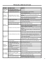
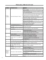
Страница 40: ... orifice Pilot will not remain lit Problem with Flame Sensor circuit Check for proper connection of the Flame Sensor to the DFC board Check pilot for full flame impingement around Flame Sensor If flame is too small check gas pressure adjust pilot rate screw check pilot head for damage Ensure the ground wire is properly attached to the pilot mounting bracket and that it is makes a good electrical c...

Страница 41: ... pressure Check wiring to thermostat for breaks Check for flame impingement on thermopile Flame lifting Leak in vent pipe Check for leaks in vent connections Improper vent configuration Check vent configuration with manual Terminal may be re circulating flue gases Check to see if terminal is on correctly May need to install high wind termination cap Contact dealer Blue Flames The heater has just b...

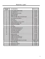
Страница 42: ...Door Gasket 10ft 50 634 12 Valve Cover with Gasket 50 2503 13 Fan Only 50 2493 14 Pilot Gasket EC 021 15 Door Latch Mechanism Set of 2 50 2507 16 120 Ceramic Fan Temp Sensor EC 001 17 885 Proflame IPI Valve NG 50 2682 18 Burner Control Module 50 2781 19 PSE IPI Pilot Assembly 50 3026 20 Remote Receiver 50 2007 E30GI Owners Manual 50 2581 E30GI Conversion Kit NG to LP 50 2487 E30GI Conversion Kit L...

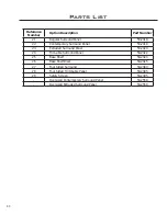
Страница 43: ... 2419 23 Extruded Surround Panel 50 2420 24 Trim able Surround Panel 50 2422 25 Base Shelf 50 2424 26 Base Shelf Riser 50 2425 27 Four Sided Surround 50 2484 28 Four Sided Trimmable Panel 50 2485 29 Safety Screen 50 2495 Oversized Contemporary Surround Panel 50 2558 Oversized Extruded Surround Panel 50 2559 Parts List ...

Страница 44: ...44 Parts Diagram Components 1 15 2 13 3 4 16 6 7 12 5 14 19 8 20 18 17 11 10 9 ...

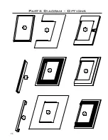
Страница 45: ...45 Parts Diagram Options 22 26 23 24 27 25 28 21 29 ...

Страница 46: ...46 NOTES ...

Страница 47: ...aler including serial number This warranty does not cover any discoloration of the safety screen mesh Exclusions An expanded list of exclusions is available at www enviro com help warranty html This warranty does not cover Damage as a result of improper usage or abuse Damage caused from over firing due to incorrect setup or tampering Damage caused by incorrect installation To the Dealer Provide na...

Страница 48: ..._____________________ MODEL ___________________________________ SERIAL NUMBER ___________________________ DATE OF PURCHASE _____________ dd mm yyyy DATE OF INSTALLATION ___________ dd mm yyyy DIRECT VENT B VENT NATURAL GAS NAT PROPANE LPG INLET GAS PRESSURE _________in WC MAIN BURNER ORIFICE __________ DMS PILOT ORIFICE _________OR________in diam INSTALLER S SIGNATURE _____________________________...

Отзывы: