TroubleShooting
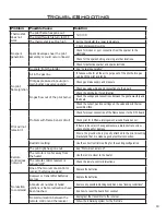
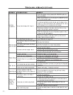
Problem
Possible Cause
Solution
Locking
conditions
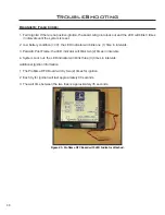
Reset the Proflame DFC board
· Turn the system off by pressing the ON/OFF button on
the transmitter
· After approximately 2 seconds press the ON/OFF button
on the transmitter again.
· In the manual flame control mode, use the down arrow
button to reduce the flame to off, indicated by the word
OFF displayed on the transmitter LCD screen.
· Wait approximately 2 seconds and press the up arrow
button, the ignition sequence will start.
· With the transmitter off, move the slider switch on the
receiver to the OFF position.
· Wait approximately 2 seconds and move the receiver
slider switch to the ON position.
Main burners
will not start
The pilot flame has gone out
· See “Pilot will not remain lit”
The remote control is not working
correctly
· Replace the batteries
The thermostat is disconnected or
set too high
· Set the thermostat to a lower temperature
Problem with thermopile circuit
· Check gas line pressure
· Check wiring to thermostat for breaks
· Check for flame impingement on thermopile
Flame lifting
Leak in vent pipe
· Check for leaks in vent connections
Improper vent configuration
· Check vent configuration with manual
Terminal may be re-circulating flue
gases
· Check to see if terminal is on correctly
· May need to install high wind termination cap.
· Contact dealer
Blue Flames
The heater has just been started
· Normal during start up: flame will yellow as the fireplace
heats up
Improper air shutter adjustment
· Adjust air shutter – contact your dealer
Glass fogs up
Normal condition: after the
appliance warms up the glass will
be clear.
**Due to additives in gas, glass may get hazy during
operation** Clean as needed.
Flames are
burning
“dirty” or
sooting
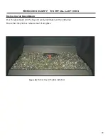
The logs or glasses are placed
incorrectly
· Check log positioning
· Check level of glasses layout
Improper air shutter adjustment
· Increase primary air by opening the air shutter and/or
by opening the vent restrictor
· Check for proper venting and blockage of the vent
termination
· See also “Burners will not remain lit”
Incorrect rating input
· Check manifold pressure and clock input rating for over-
firing
41
Содержание E30GI
Страница 26: ...26 Initial Installation QUALIFIED INSTALLERS ONLY 5 of 10 Figure 30 Wiring Schematic ...
Страница 44: ...44 Parts Diagram Components 1 15 2 13 3 4 16 6 7 12 5 14 19 8 20 18 17 11 10 9 ...
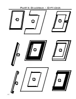
Страница 45: ...45 Parts Diagram Options 22 26 23 24 27 25 28 21 29 ...
Страница 46: ...46 NOTES ...

