21
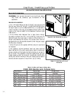
Table 4: Vent termination clearances
Minimum Clearance
Description
3 ft (0.9 m)
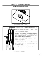
Clearance above the highest point where it passes through a roof surface, refer to
Figure 23.
24 in (0.6 m)
Clearance above a roof ridge, any other portion of a building, or any other obstruc
-
tion within a horizontal distance of 10 feet (3 m), refer to Figure 23.
5 ft (1.5 m)
Clearance for a vent or chimney above either the highest connected appliance
drafthood outlet, or flue collar.
6 ft (1.83 m)
Clearance to mechanical air supply inlet.
3ft (0.9m)
Clearance to each side of center line extended above meter/regulator assembly.
6 ft (1.83 m)
Radial clearance around service regulator vent outlet.
12 in (30 cm)
Clearance above grade, verandah, porch, deck, or balcony.
3 ft (0.9 m)
Clearance to a building opening or combustion air inlet of another appliance, ex
-
cept with the approval of the authority having jurisdiction for the following reduced
clearances.
9 in (0.23 m)
Exception for inputs up to and including 50,000 Btu/h (15kW)
12 in (0.3 m)
Exception for inputs exceeding 50,000 Btu/h (15kW) but not exceeding 100,000
Btu/h (30kW)
V
enting
f
iRepLace
i
nseRts
:
The ENVIRO
E30GI may be installed and vented into any solid fuel fireplace that has been installed
in accordance with the National, Provincial/State and local building codes and has been constructed of
non-combustible materials. Before starting, refer to
I
nItIal
I
nstallatIon
- p
reparIng
y
our
e30gI F
or
I
nstallatIon
.
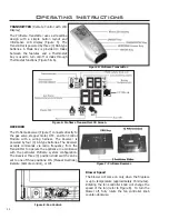
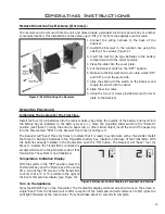
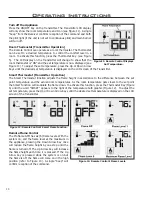
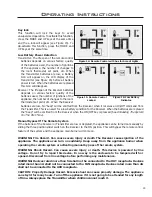
Please reference the information in Table 4 and Figures 23, and 25.
An approved chimney liner and rain cap must be used. A throat connector or flashing
must
be installed to
ensure a tight seal, top performance, safety and efficiency. Carefully follow the manufacturer’s instructions
that accompany the chimney liner kit. Use double walled aluminum flex vent (3” flex conversion piece and
4”x 6 5/8” cap) from any of the following approved products; Simpson Dura-Vent (Direct Vent GS) or (ICC
Excel Direct). If necessary, remove the vent collar plate from the top of the insert and connect it securely
to the liner with sheet metal screws.
Check for any tears in the liner at this point. IMPORTANT: The screws that hold the vent collar plate in its
approved position must be installed.
Initial Installation
QUALIFIED INSTALLERS ONLY
NOTE:
If the E30GI unit is pulled out of its installation, and the vent air intake system is disconnected
for any reason, ensure that the vent-air intake pipes are re-sealed with high-temperature sealant and
reconnected with three (3) sheet metal screws evenly spaced.
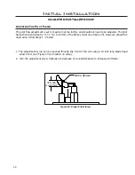
2ft (0.6m)
Minimum
3ft (0.9m)
Minimum
Within
10ft (3m)
Roof ridge or
any other portion
of a building
Figure 23: Roof Clearances.
Содержание E30GI
Страница 26: ...26 Initial Installation QUALIFIED INSTALLERS ONLY 5 of 10 Figure 30 Wiring Schematic ...
Страница 44: ...44 Parts Diagram Components 1 15 2 13 3 4 16 6 7 12 5 14 19 8 20 18 17 11 10 9 ...
Страница 45: ...45 Parts Diagram Options 22 26 23 24 27 25 28 21 29 ...
Страница 46: ...46 NOTES ...

