19/22
AMF 3.1 USER MANUAL
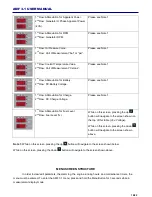
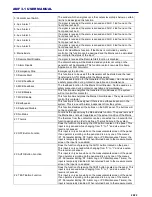
there are 1200 hours left until general maintenance.
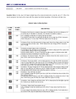
The second timer is the Engine Maintenance Timer and is indicated as “Eng” as seen on the screen on the
left.
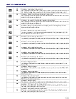
A few seconds after this indication the second screen seen on the left will appear. The screen indicates that
there are 1200 hours left until engine maintenance.
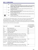
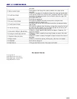
The third timer is the Total Engine Running Hours and is indicated as “tEn” as seen on the screen on the left.
A few seconds after this indication the second screen seen on the left will appear. The screen indicates that
the engine has been running for 1200 hours.
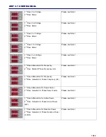
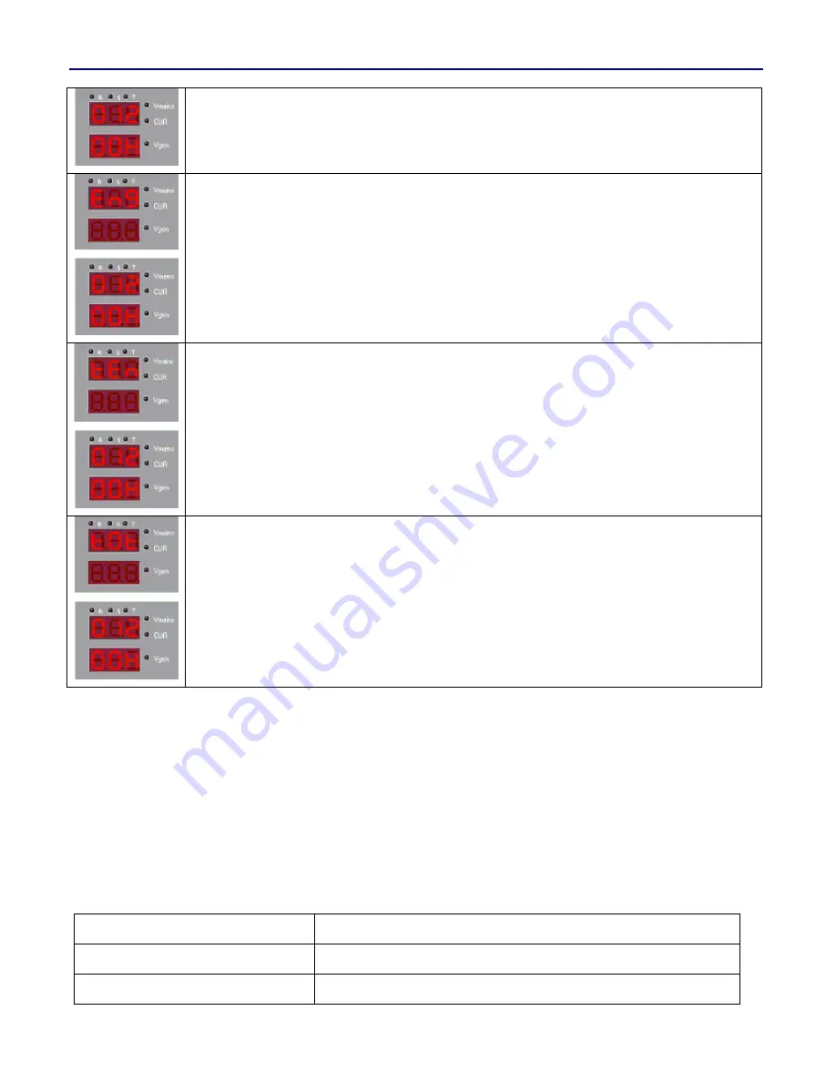
The fourth timer is the Total System Running Hours and is in
dicated as “t0t” as seen on the screen on the left.
A few seconds after this indication the second screen seen on the left will appear. The screen indicates that
the system has been running for a total of 1200 hours.
Digital Input Functions & Descriptions
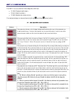
The inputs indicating “AUX INPUT” on the back panel are the digital inputs of the panel. These inputs are optically
isolated. “COM 7” is the common for auxiliary inputs 1,2,3 and 4. “COM 8” is the common for auxiliary inputs 5 and
6. In typical Generator applications, the COM 7 and COM 8 will be connected to the (+) terminal of the battery, and
the auxiliary inputs will be connected with senders connected to the chasis. The following functions can be
assigned to the auxiliary inputs using their respective parameters P206, P212, P218, P224, P230 and P236.
Note:
The same function should not be assigned to more than 1 input. If there are the same functions assigned to
multiple terminals, that function will not work properly.
The following functions can be assigned to auxiliary inputs.
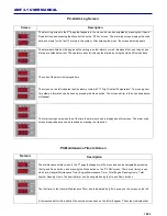
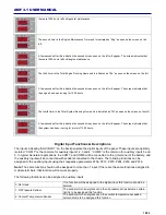
0: Not Used
If no function will be assigned to the digital input, this function should be
selcted.
1: Oil Pressure Sender
The sender which energizes once the oil pressure drops below a certain
limit is to be assigned this function.
2: Coolant Temperature Sender
The sender which energizes once the coolant temperature exceeds a
certain limit is to be assigned this function.
Содержание AMF 3.1
Страница 1: ...AMF 3 1 EN K K 01 KO AMF 3 1 User Manual...
Страница 4: ...4 22 AMF 3 1 USER MANUAL Connection Diagram...

