17/22
AMF 3.1 USER MANUAL
The AMF 3.1 menu consisit of 3 main categories which are:
P1 PAR: Parameter edit screen
P2 ALR: Alarm log screen
P3 SER: Maintenance timers screen
The desired category can be selected using the Up
and Down
Arrow buttons.
P1: PARAMETER EDIT SCREEN
Screen
Description
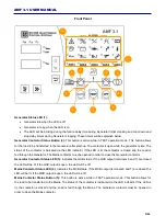
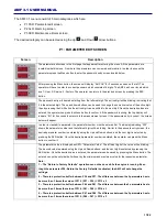
The parameter edit screen is the first page that appears after entering the menu. All the parameters are
located inside this menu. From here the parameters can ve viewed and/or edited. In order to access the
parameters press the Menu button to enter the password entry screen located below.
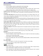
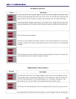
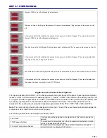
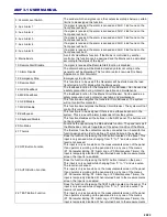
After pressing the Menu button, the screen will display “Ent PAS” for 2 seconds as seen on the left. The
operator will have to enter the correct password which consists of 4 digits. The AMF has 3 user levels which
are 1- User, 2- Service, 3- Factory. The operator can return to the previous screen by pressing the ESC
button.
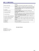
The password entry will be made starting from the leftmost digit. The active digit will be blinking, indicating that
it is the selected digit. The up and down buttons can be used to change the numerical value of the active digit,
then by pressing the Shift button the active digit can be shifted to the next digit. Once the desired values are
entered, the operator can press the Menu button to confirm it. If the password is wrong, the top display will
indicate “Err” for 2 seconds then return to the measurement screen. If the password entry is correct, the screen
below will appear.
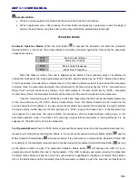
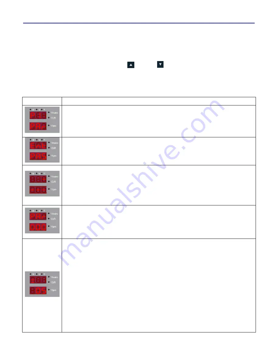
In order to view/edit a parameter, the parameter number must be entered first. The display indicating “000”
shows the parameter number and the leftmost digit will be blinking. Similar to the password entry screen, the
desired parameter number is entered by using the Up and Down buttons, and the next digit is selected by
pressing the Shift button. Once the desired parameter number is entered, the operator can press the Menu
button to confirm it.
The parameter value is displayed as SET= “Parameter Value”. The leftmost digit of the value will be blinking.
The desired value is entered using the Up and Down buttons, and the next digit is selected by pressing the
Shift button. Once the desired value is entered, the parameter can be saved by pressing the Menu button. The
entered can not be outside the limits set by the minimum and maximum value for the respective parameter.
Note :
1
– The “Return to Factory Defaults” operation can not be done while the engine is running. Even
thogh the parameter P30: Return the Factory Defaults is activated, the AMF will not change the
settings.
2
– There is a protection buffer between P36 and P37. The difference between the 2 parameters has to
be more than 3 times the value of P313. (P37
– P36) > P313 x 3
3
– There is a protection buffer between P40 and P41. The difference between the 2 parameters has to
be more than 3 times the value of P314. (P41
– P40) > P314 x 3
4
– There is a protection buffer between P47 and P48. The difference between the 2 parameters has to
be more than 3 times the value of P315. (P48
– P47) > P315 x 3
Содержание AMF 3.1
Страница 1: ...AMF 3 1 EN K K 01 KO AMF 3 1 User Manual...
Страница 4: ...4 22 AMF 3 1 USER MANUAL Connection Diagram...

