


22/22
AMF 3.1 USER MANUAL
activated.
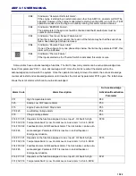
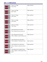
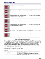
9: Mains Loaded Output
If the system is fed through the mains contactor, this output will be
activated.
10: Fuel Pump Output
If there is a requirement of automatic fueling this output will be activated.
If the fuel level drops below the limit set by parameter P300 this output is
activated and is deactivated when the fuel level reaches the upper limit
set by parameter P301.
11: Undefined
No function is assigned.
12: Louvre Control Output
This output is activated when the fuel solenoid is energized and
deactivated when the engine stos.
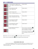
13: Fuel Solenoid Output
The same functions as the Fuel Solenoid output can be assigned using
this function.
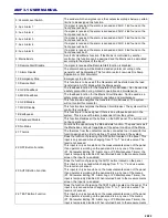
14: Telecom Running
This output is activated once the battery voltage drops below the limit set
by P26 and is deactivated once the voltage reaches the limit set by P27.
There is a 5 second delay between levels.
15: Generator Voltage or Speed Alarm
If there is an alarm regarding the generator voltages or frequency, this
output is activated.
16: Analog Low Oil Pressure Alarm
If there is an alarm caused by the analog oil pressure sender, this alarm
is activated.
17: Digital Oil Pressure Alarm
If there is an alarm caused by the digital oil pressure switch, this alarm is
activated.
18: Speed Alarm
If there is and alarm caused by the frequency, this alarm is activated.
19: Undefined
No function is assigned.
20: Start Failure
If the generator failed to start, this output is activated.
Document Version
Versiyon No : 01
Değişiklik Tarihi : 05.05.2014
Değişikliği Yapan : Hasip TUNA
Değişiklik Nedeni : Yayım
Содержание AMF 3.1
Страница 1: ...AMF 3 1 EN K K 01 KO AMF 3 1 User Manual...
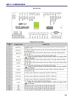
Страница 4: ...4 22 AMF 3 1 USER MANUAL Connection Diagram...