TMT182
1 Safety notes
Hauser
11
3.2.2
Typical North American installation
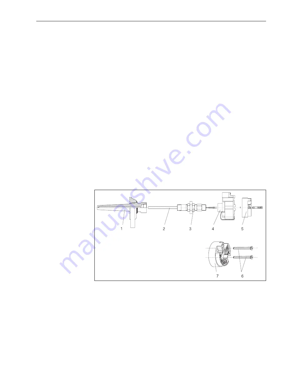
Industrial thermocouple or RTD assembly with head transmitter (see fig. 5)
• Attach the thermowell (Pos. 1) to the pipe or process container wall. Install and tighten thermo-
wells before applying process pressure.
• Attach necessary extension nipples and adapters (Pos. 3) to the thermowell. Seal the nipple and
adapter threads with silicone tape.
• Install drain seals if required for severe environments or to satisfy code requirements.
• Feed the installation screws (Pos. 6) through the holes in the head transmitter (Pos. 7).
• Position the head transmitter assembly in the transmitter housing (Pos. 4) in such a way so that
the current output terminals (terminal 1 and 2) are towards the conduit.
• Screw the head transmitter assembly (Pos. 5) into the the transmitter housing (Pos. 4) using a
screwdriver.
• Feed the sensor inset cables through the conduit of the transmitter housing and the central hole
in the head transmitter.
• Attach the transmitter housing (Pos. 4) with built in head transmitter assembly to the nipples and
adapters (Pos. 3). Seal adapter threads with silicone tape.
"
Caution!
In order to avoid damaging the head transmitter, do not over-tighten the installation screws.
"
Caution!
Pull the field wiring leads through the conduit into the transmitter housing. Attach the sensor and
power leads to the head transmitter. Avoid contact with other terminals.
"
Caution!
Install and tighten the transmitter housing cover. Enclosure covers must be fully engaged to meet
explosion-proof requirements.
ƒig. 5:
: Installing the head transmitter - Head transmitter assembly
Pos. 1: Thermowell
Pos. 2: Measuring inset
Pos. 3: Extension neck
Pos. 4: Transmitter housing
Pos. 5: Head transmitter assembly
Pos. 6: Installation screws
Pos. 7: Head transmitter


