ICM/ICAD Motorized Valve
Installation, Programming, and Troubleshooting
4
DKRCI.EI.HT0.A1. / 50H1639
Danfoss (USCO / MKS), 11- 006
Care should be taken to protect the ICM function module while it is removed from the
valve body.
3. Weld the valve body in line making sure the arrow on the valve body is pointing in
the direction of flow.
4. Remove all debris from the valve body before re-installing the bonnet.
5. Install the bonnet/function module into the valve body.
a. For ICM 0, make sure that the removable orifice seat is installed in the valve body
with the small O-ring between the orifice seat and body. Make sure the bonnet gasket
is installed and in good condition.
b. For ICM 5 through ICM 65, check that the two O-rings on the bonnet and gasket
located between the bonnet and valve body are installed and in good condition. A
light coating of refrigerant oil on the bonnet O-rings will facilitate installation of the
bonnet.
6. Install the four bolts and torque to the following specifications:
Valve body
Nm
ft lbs
ICM 0
50
37
ICM 5
80
59
ICM 3
80
59
ICM 40
90
66
ICM 50
100
74
ICM 65
110
81
7. Install the ICAD motor actuator on the ICM valve:
a. The ICM valve must not be in its fully opened position while the ICAD motor is
calibrated with the valve at a later step. Therefore, if the opening degree of the ICM
valve was changed from the factory setting, it should be set to an opening degree
between 0% and 75% using the manual magnet tool. To easily ensure correct
positioning, turn the manual tool counter-clockwise until it is clear that it cannot be
turned further.
b. Make sure that the ICM adapter/valve stem and inner ICAD motor magnets are
completely dry and free from any debris.
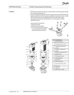
c. For applications below freezing, the ICM adapter O-ring (position c in the diagram
on page 3) must be removed, and Molycote G 4500 grease (supplied with ICAD
motor) needs to be applied in the O-ring groove on the adapter and on the O-ring
before it is re-installed on the ICM adapter. The Molycote grease ensures a good seal
between the ICAD motor and the ICM adapter to prevent moisture from entering the
ICAD magnets.
d. Place the ICAD motor on the valve stem.
e. Push the ICAD motor completely down to the identification ring on the valve stem
and use a .5 mm hex key to tighten the set screws evenly so the ICAD motor is
centered on the ICM adapter (torque: 3 Nm/ .5 lb-ft).
Содержание Vilter VSH
Страница 2: ......
Страница 30: ...2 4 Blank VSS VSM VSH VSSH Installation Operation and Maintenance Manual Emerson 35391SD ...
Страница 54: ...3 24 Blank VSS VSM VSH VSSH Installation Operation and Maintenance Manual Emerson 35391SD ...
Страница 74: ...4 20 Blank VSS VSM VSH VSSH Installation Operation and Maintenance Manual Emerson 35391SD ...
Страница 144: ...5 70 Blank VSS VSM VSH VSSH Installation Operation and Maintenance Manual Emerson 35391SD ...
Страница 156: ...7 4 Blank VSS VSM VSH VSSH Installation Operation and Maintenance Manual Emerson 35391SD ...
Страница 158: ...8 2 Blank VSS VSM VSH VSSH Installation Operation and Maintenance Manual Emerson 35391SD ...
Страница 204: ...8 48 Blank VSS VSM VSH VSSH Installation Operation and Maintenance Manual Emerson 35391SD ...
Страница 206: ...A 2 Blank VSS VSM VSH VSSH Installation Operation and Maintenance Manual Emerson 35391SD ...
Страница 210: ...B 4 Blank VSS VSM VSH VSSH Installation Operation and Maintenance Manual Emerson 35391SD ...
Страница 216: ...C 6 Blank VSS VSM VSH VSSH Installation Operation and Maintenance Manual Emerson 35391SD ...
Страница 219: ......
Страница 221: ......
Страница 224: ......
Страница 225: ......
Страница 226: ......
Страница 242: ...E 12 Blank VSS VSM VSH VSSH Installation Operation and Maintenance Manual Emerson 35391SD ...
Страница 248: ...G 2 Blank VSS VSM VSH VSSH Installation Operation and Maintenance Manual Emerson 35391SD ...
Страница 249: ......


