


4 – 7
Section 4 • Operation
VSS/VSM/VSH/VSSH • Installation, Operation and Maintenance Manual • Emerson • 35391SD
NOTE
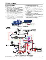
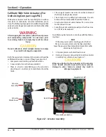
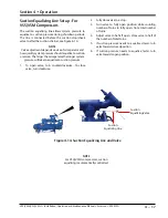
If the “+” (increase) and “-” (decrease) buttons do not
correspond to increase or decrease shaft rotation,
swap the blue and brown wires of the “power cable” in
the control panel. This will reverse the rotation of the
actuator/command shaft, see Figure 4-5.
Capacity actuator wires are connected on terminals
13 & 14. Volume actuator wires are connected on
terminals 15 & 16.
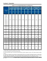
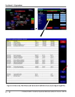
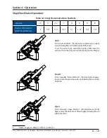
7. Press “+” or “-” to move the slide valve and check
for the correct rotation, see Table 4-1.
NOTE
When the actuator is in calibration mode, it outputs
0 V when the actuator is running and 5 V when it is
still. Thus, as stated earlier, the actuator voltage will
fluctuate during calibration. After the actuator has been
calibrated, 0 V output will correspond to the minimum
position and 5 V to the maximum position.
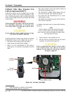
8. Quickly press and release the blue push button on
the actuator one time. This places the actuator in
calibration mode. The red LED will begin flashing
rapidly.
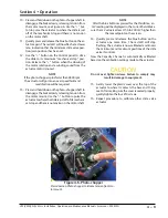
CAUTION
DO NOT CONTINUE TO ENERGIZE THE ACTUATOR
MOTOR AFTER THE SLIDE HAS REACHED THE
MECHANICAL STOP. Doing so may cause mechanical
damage to the motor or shear the motor shaft key.
When the slide has reached the mechanical stop
position, press the button in the center of the photo-
chopper to release the brake, and thereby release the
tension on the actuator motor.
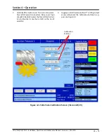
NOTE
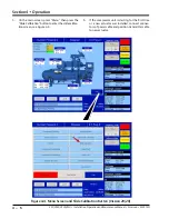
The “Slide Calibration” screen on the Control Panel
has a “Current” window, which displays the actuator
output voltage. These values, (the % volume and the %
capacity) displayed in the window are meaningless until
calibration has been completed.
9.
Use the “-” button on the Control panel to drive the
slide valve to its minimum “mechanical stop” po-
sition. Release the “-” button when the slowing of
the motor rotation and a winding sound from the
actuator motor is noted.
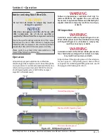
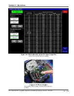
Figure 4-5. Wire Connections for Capacity and Volume Actuators
Volume Actuator
Wire connections
(15, 16)
Capacity Actuator
Wire connections
(13, 14)
Содержание Vilter VSH
Страница 2: ......
Страница 30: ...2 4 Blank VSS VSM VSH VSSH Installation Operation and Maintenance Manual Emerson 35391SD ...
Страница 54: ...3 24 Blank VSS VSM VSH VSSH Installation Operation and Maintenance Manual Emerson 35391SD ...
Страница 74: ...4 20 Blank VSS VSM VSH VSSH Installation Operation and Maintenance Manual Emerson 35391SD ...
Страница 144: ...5 70 Blank VSS VSM VSH VSSH Installation Operation and Maintenance Manual Emerson 35391SD ...
Страница 156: ...7 4 Blank VSS VSM VSH VSSH Installation Operation and Maintenance Manual Emerson 35391SD ...
Страница 158: ...8 2 Blank VSS VSM VSH VSSH Installation Operation and Maintenance Manual Emerson 35391SD ...
Страница 204: ...8 48 Blank VSS VSM VSH VSSH Installation Operation and Maintenance Manual Emerson 35391SD ...
Страница 206: ...A 2 Blank VSS VSM VSH VSSH Installation Operation and Maintenance Manual Emerson 35391SD ...
Страница 210: ...B 4 Blank VSS VSM VSH VSSH Installation Operation and Maintenance Manual Emerson 35391SD ...
Страница 216: ...C 6 Blank VSS VSM VSH VSSH Installation Operation and Maintenance Manual Emerson 35391SD ...
Страница 219: ......
Страница 221: ......
Страница 224: ......
Страница 225: ......
Страница 226: ......
Страница 242: ...E 12 Blank VSS VSM VSH VSSH Installation Operation and Maintenance Manual Emerson 35391SD ...
Страница 248: ...G 2 Blank VSS VSM VSH VSSH Installation Operation and Maintenance Manual Emerson 35391SD ...
Страница 249: ......