


5 – 43
Section 5 • Maintenance/Service
VSS/VSM/VSH/VSSH • Installation, Operation and Maintenance Manual • Emerson • 35391SD
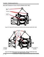
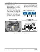
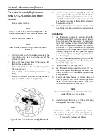
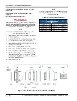
required on VSS 451 thru 601. For the VSS 751 thru
901 and VSS 1051 thru 1301 compressors, use the
side rails and assemble to the gaterotor stabilizer as
stamped. For the VSS 1551 thru 2101, use the side
rails and assemble to the gaterotor stabilizer. Refer
to Figure 5-40.
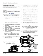
7. Remove hex head bolts and socket head bolts from
thrust bearing cover.
8. Re-install two bolts into the threaded jacking holes
to assist in removing thrust bearing cover. Retain
the shim pack.
9. Hold gaterotor support with a suitable wrench on
the flats provided near the roller bearing housing.
10. Remove the inner retainer bolts and retainer.
11. To remove the thrust bearing housing, install thrust
bearing removal and installation tool with smaller
puller shoe. Turn the jacking screw clockwise. The
thrust bearings and housing assembly will be pulled
off the shaft and out of the frame.
12. Remove bolts from roller bearing housing.
13. Re-install two bolts into jack bolt holes provided in
housing to aid in removal.
14. To remove the gaterotor support, carefully move
support in the opposite direction of rotation and
tilt roller bearing end towards the suction end of
the compressor. The compressor input shaft may
have to be turned to facilitate the removal of the
gaterotor support. On dual gate compressor units,
repeat the procedure for the remaining gaterotor
support assembly.
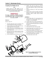
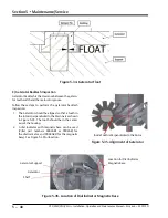
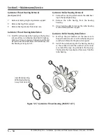
Installation
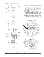
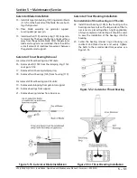
15. Install gaterotor support by carefully tilting the
roller bearing end of the gaterotor support towards
the suction end of the compressor. The compressor
input shaft may have to be rotated to facilitate the
installation of the gaterotor support. Install gatero-
tor stabilizer. The gaterotor stabilizer (901) will hold
the gaterotor support in place as the thrust bearing
housing is being installed. If the gaterotor support
is not restricted from moving, the gaterotor blade
may be damaged. See Figure 5-41.
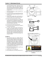
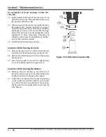
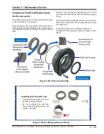
16. Install the roller bearing housing (112) with a new
O-ring (141). See Figure 5-42.
17. Tighten bolts (152), see Appendix A.
18. When installing the thrust bearing housing (113), a
!
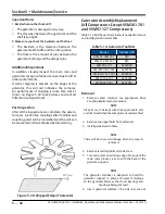
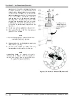
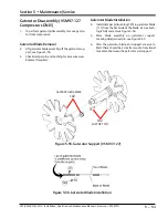
WARNING
Blades on gaterotor are
sharp.
90 1C
90 1B
90 1A
Figure 5-40. Gaterotor Assembly Removal
and Tools
For VSS 451-601
compressors, do not
use side rails.
For VSS 751/901 and 1051-
1301 compressors, use side
rails and assemble gaterotor
stabilizer as stamped.
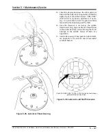
Position leading edge of main rotor groove
flush with or slightly below back of gaterotor
support.
Содержание Vilter VSH
Страница 2: ......
Страница 30: ...2 4 Blank VSS VSM VSH VSSH Installation Operation and Maintenance Manual Emerson 35391SD ...
Страница 54: ...3 24 Blank VSS VSM VSH VSSH Installation Operation and Maintenance Manual Emerson 35391SD ...
Страница 74: ...4 20 Blank VSS VSM VSH VSSH Installation Operation and Maintenance Manual Emerson 35391SD ...
Страница 144: ...5 70 Blank VSS VSM VSH VSSH Installation Operation and Maintenance Manual Emerson 35391SD ...
Страница 156: ...7 4 Blank VSS VSM VSH VSSH Installation Operation and Maintenance Manual Emerson 35391SD ...
Страница 158: ...8 2 Blank VSS VSM VSH VSSH Installation Operation and Maintenance Manual Emerson 35391SD ...
Страница 204: ...8 48 Blank VSS VSM VSH VSSH Installation Operation and Maintenance Manual Emerson 35391SD ...
Страница 206: ...A 2 Blank VSS VSM VSH VSSH Installation Operation and Maintenance Manual Emerson 35391SD ...
Страница 210: ...B 4 Blank VSS VSM VSH VSSH Installation Operation and Maintenance Manual Emerson 35391SD ...
Страница 216: ...C 6 Blank VSS VSM VSH VSSH Installation Operation and Maintenance Manual Emerson 35391SD ...
Страница 219: ......
Страница 221: ......
Страница 224: ......
Страница 225: ......
Страница 226: ......
Страница 242: ...E 12 Blank VSS VSM VSH VSSH Installation Operation and Maintenance Manual Emerson 35391SD ...
Страница 248: ...G 2 Blank VSS VSM VSH VSSH Installation Operation and Maintenance Manual Emerson 35391SD ...
Страница 249: ......