3 – 21
Section 3 • Installation
VSS/VSM/VSH/VSSH • Installation, Operation and Maintenance Manual • Emerson • 35391SD
Unit Initial Oil Charging
(Reference Figure 3-17)
10. At initial start up, compressor unit must be off and
depressurized prior to initial oil charging.
11. Using a properly selected oil pump, connect oil
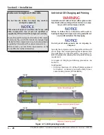
pump to oil separator drain valve (10) (for oil sepa
-
rator drain valve location, see Figure 3-16).
12. Open oil separator drain valve (10) and fill oil separa
-
tor (1) to Maximum NON-Operating Level.
13. Once Maximum NON-Operating Level has been
reached, shut off oil pump, close oil separator drain
valve (10) and remove oil pump.
14. If equipped with remote oil cooler, refer to Priming
Compressor Units Equipped with Remote Oil Cooler
procedure (see Appendix G).
Priming Oil Lines and Compressor
Continue with the following steps to prime the oil lines
and compressor:
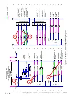
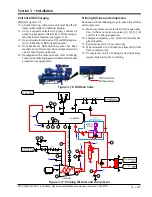
15. Make sure valves on oil circuit are in the open posi
-
tion. In this case, make sure valves (2), (3), (5), (6)
and (7) are in the open position.
16. Energize compressor unit. Vission 20/20 will ener
-
gize oil heaters.
17. Run oil pump (4) for 15 seconds only.
18. Wait minimum of 30 minutes to allow oil to drain
from compressor (8).
19. If compressor unit is not being started right away,
repeat steps 6 to 9 prior to starting.
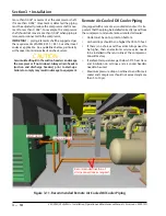
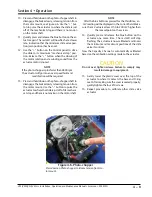
Figure 3-16. Oil Drain Valve
Oil Drain Valve
(Oil Separator)
Figure 3-17. Priming Oil Lines and Compressor
LG
001
LG
002
FG
001
PI
003
DRAIN
TW
BLEED
MW
BLEED
TW
D100
OIL CHARGE
BLEED
CAPACITY
TW
750W
TW
250#
C100
V100
VOLUME
SUCTION
STOP VALVE
DISCHARGE STOP VALVE
D101
P100
TW
750W
TW
750W
DRAIN
DISCHARGE CHECK VALVE
PI
002
PI
001
TE
001
TE
004
QE
003
TE
005
PI
004
BLEED
PT
004
PT
003
PT
002
D102
D103
TW
TE
002
QE
001
QE
002
OIL SEPARATOR
COALESCING OIL
RETURN LINE
HIGH PRESSURE
R717 VAPOR OUTLET
R717 VAPOR
TO ATMOSPHERE
LOW PRESSURE
R717 VAPOR INLET
PT
001
COMPRESSOR
MOTOR
FIL
TER
MOTOR AND
OIL PUMP
T
E100
R717 LIQUID
INLET
R717 LIQUID/VAPOR
OUTLET
100
PSID
SUCTION
CHECK VALVE
OPTIONAL
(STANDARD FOR BOOSTER &
SWING COMPRESSORS ONLY)
4
1
10
2
5
3
9
8
7
6
Содержание Vilter VSH
Страница 2: ......
Страница 30: ...2 4 Blank VSS VSM VSH VSSH Installation Operation and Maintenance Manual Emerson 35391SD ...
Страница 54: ...3 24 Blank VSS VSM VSH VSSH Installation Operation and Maintenance Manual Emerson 35391SD ...
Страница 74: ...4 20 Blank VSS VSM VSH VSSH Installation Operation and Maintenance Manual Emerson 35391SD ...
Страница 144: ...5 70 Blank VSS VSM VSH VSSH Installation Operation and Maintenance Manual Emerson 35391SD ...
Страница 156: ...7 4 Blank VSS VSM VSH VSSH Installation Operation and Maintenance Manual Emerson 35391SD ...
Страница 158: ...8 2 Blank VSS VSM VSH VSSH Installation Operation and Maintenance Manual Emerson 35391SD ...
Страница 204: ...8 48 Blank VSS VSM VSH VSSH Installation Operation and Maintenance Manual Emerson 35391SD ...
Страница 206: ...A 2 Blank VSS VSM VSH VSSH Installation Operation and Maintenance Manual Emerson 35391SD ...
Страница 210: ...B 4 Blank VSS VSM VSH VSSH Installation Operation and Maintenance Manual Emerson 35391SD ...
Страница 216: ...C 6 Blank VSS VSM VSH VSSH Installation Operation and Maintenance Manual Emerson 35391SD ...
Страница 219: ......
Страница 221: ......
Страница 224: ......
Страница 225: ......
Страница 226: ......
Страница 242: ...E 12 Blank VSS VSM VSH VSSH Installation Operation and Maintenance Manual Emerson 35391SD ...
Страница 248: ...G 2 Blank VSS VSM VSH VSSH Installation Operation and Maintenance Manual Emerson 35391SD ...
Страница 249: ......

