TOC - 8
VSS/VSM/VSH/VSSH • Installation, Operation and Maintenance Manual • Emerson • 35391SD
Table of Contents
Table / Figure
Page Number
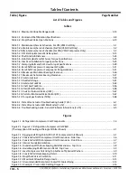
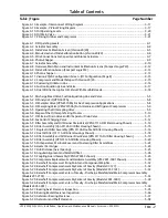
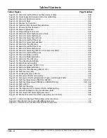
Figure 5-31. Gaterotor and Shelf Clearance Measurement Steps ............................................................... 5-38
Figure 5-32. Visual Inspection Between Gaterotor and Bushing ................................................................ 5-39
Figure 5-33. Gaterotor Float Dial Location ................................................................................................ 5-39
Figure 5-34. Gaterotor Float ..................................................................................................................... 5-40
Figure 5-35. Alignment of Gaterotor ........................................................................................................ 5-40
Figure 5-36. Location of Dial Indicator Magnetic Base ............................................................................... 5-40
Figure 5-37. Placement of Dial Indicator ................................................................................................... 5-41
Figure 5-38. Measuring Backlash .............................................................................................................. 5-41
Figure 5-39. Chipped Edge of Gaterotor ................................................................................................... 5-42
Figure 5-40. Gaterotor Assembly Removal and Tools ................................................................................ 5-43
Figure 5-41. Gaterotor Assembly Removal ............................................................................................... 5-44
Figure 5-42. Gaterotor Assembly and Tools .............................................................................................. 5-45
Figure 5-43. Gaterotor and Shelf Clearance .............................................................................................. 5-45
Figure 5-44. Gaterotor Assembly Breakdown ........................................................................................... 5-46
Figure 5-45. Gaterotor Thrust Bearing ...................................................................................................... 5-47
Figure 5-46. Gaterotor and Shelf Clearance .............................................................................................. 5-47
Figure 5-47. Gaterotor Assembly Removal ............................................................................................... 5-48
Figure 5-48. Gaterotor Assembly (VSM 97-127 Compressors ONLY) ......................................................... 5-49
Figure 5-49. Gaterotor and Shelf Clearance .............................................................................................. 5-50
Figure 5-50. Gaterotor Blade Assembly .................................................................................................... 5-50
Figure 5-51. Gaterotor Blade Installation .................................................................................................. 5-51
Figure 5-52. Gaterotor Thrust Bearing ...................................................................................................... 5-51
Figure 5-53. Thrust Bearing Installation .................................................................................................... 5-51
Figure 5-54. Roller Bearing Assembly ....................................................................................................... 5-52
Figure 5-55. Gaterotor Support (VSM 97-127) .......................................................................................... 5-53
Figure 5-56. Gaterotor Blade Installation .................................................................................................. 5-53
Figure 5-57. Gaterotor Thrust Bearing (VSM 97-127) ................................................................................ 5-54
Figure 5-58. Shaft Seal Assembly.............................................................................................................. 5-55
Figure 5-59. Handling Seal Face with Care ................................................................................................ 5-55
Figure 5-60. Compressor Shaft Seal Assembly .......................................................................................... 5-56
Figure 5-61. Compressor Shaft Seal Installation: Tapered and Straight Shafts ........................................... 5-57
Figure 5-62. Shaft Seal Breakdown (28985Y & 28985YA) .................................................................. 5-58,5-61
Figure 5-63. Shaft Seal Breakdown (28985W and 28985WA Only) .................................................. 5-59, 5-62
Figure 5-64. Shaft with Pin ....................................................................................................................... 5-60
Figure 5-65. Shaft Seal Housing................................................................................................................ 5-60
Figure 5-66. The Alignment of Compressor Shaft and Mating Ring ........................................................... 5-60
Figure 5-67. Actuator Installation Using Anti-Rotation Bolts ..................................................................... 5-64
Figure 5-68. Command Shaft Assembly Replacement .............................................................................. 5-65
Figure 5-69. Danfoss ICF 20-40 Valve Station (Liquid Injection Control) .................................................... 5-66
Figure C-1. Compressor Bearing Vibration Measurement Location...............................................................C-1
Figure C-2. Main Rotor Cross-Section VSS/VSM Compressors ......................................................................C-2
Figure C-3. Gaterotor Cross-Section VSS/VSR/VSM Compressors .................................................................C-3
Содержание Vilter VSH
Страница 2: ......
Страница 30: ...2 4 Blank VSS VSM VSH VSSH Installation Operation and Maintenance Manual Emerson 35391SD ...
Страница 54: ...3 24 Blank VSS VSM VSH VSSH Installation Operation and Maintenance Manual Emerson 35391SD ...
Страница 74: ...4 20 Blank VSS VSM VSH VSSH Installation Operation and Maintenance Manual Emerson 35391SD ...
Страница 144: ...5 70 Blank VSS VSM VSH VSSH Installation Operation and Maintenance Manual Emerson 35391SD ...
Страница 156: ...7 4 Blank VSS VSM VSH VSSH Installation Operation and Maintenance Manual Emerson 35391SD ...
Страница 158: ...8 2 Blank VSS VSM VSH VSSH Installation Operation and Maintenance Manual Emerson 35391SD ...
Страница 204: ...8 48 Blank VSS VSM VSH VSSH Installation Operation and Maintenance Manual Emerson 35391SD ...
Страница 206: ...A 2 Blank VSS VSM VSH VSSH Installation Operation and Maintenance Manual Emerson 35391SD ...
Страница 210: ...B 4 Blank VSS VSM VSH VSSH Installation Operation and Maintenance Manual Emerson 35391SD ...
Страница 216: ...C 6 Blank VSS VSM VSH VSSH Installation Operation and Maintenance Manual Emerson 35391SD ...
Страница 219: ......
Страница 221: ......
Страница 224: ......
Страница 225: ......
Страница 226: ......
Страница 242: ...E 12 Blank VSS VSM VSH VSSH Installation Operation and Maintenance Manual Emerson 35391SD ...
Страница 248: ...G 2 Blank VSS VSM VSH VSSH Installation Operation and Maintenance Manual Emerson 35391SD ...
Страница 249: ......


