Safety
Information
Introduction
Product
information
System
design
Mechanical
installation
Electrical
installation
Getting
started
Optimisation
Parameters
Technical
data
Component
sizing
Diagnostics
20
Unidrive SP Regen Installation Guide
www.controltechniques.com Issue Number: 2
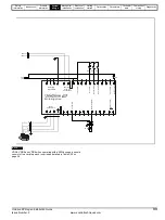
The 24V supply must be protected using a 4A slow-blow fuse, one for each supply pole.
Control connections to the Unidrive SPMC/U should be made with 0.5mm
2
cable.
The status relay contacts are rated for switching non-inductive loads at 250Vac 6A non-inductive, up to 4Adc if the voltage is limited to 40V or up to
400mA dc if the voltage is limited to 250Vdc. Protection from overcurrent must be provided.
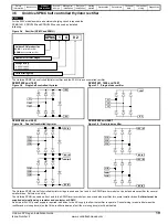
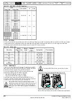
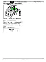
Figure 3-9 SPMC/U rating label
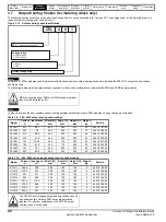
3.6 Unidrive SPMC/U technical data
Table 3-5 Unidrive SPMC / U input current, fuse and cable ratings
Status1
Status0
I/P 380-480V
50-60Hz
3ph 204A
O/P 513-648V 552A
SPMC1402
Ser No:
3000005001
STDN39
Customer and
date code
Serial
number
Approvals
Input voltage, frequency,
no. of phases and current
Output voltage
and current
Status
LEDs
Model:
SPMC = Controlled
Voltage
rating:
4 - 400V
Number of
rectifier
stages
Indicates
sub-rating
within frame
size
SPMU = Uncontrolled
6 - 690V
Model
Typical input
current
A
Maximum
input current
A
Typical DC
current
Adc
Semi-conductor fuse
in series with HRC fuse
Cable sizes
AC input
DC output
HRC IEC
class gG UL
class J
Semi-
conductor
IEC class aR
mm
2
AWG
mm
2
AWG
SPMC1402
339
344
379
540
400
2 x 120 2 x 4/0
2 x 120
2 x 4/0
SPMC2402
2 x 308
2 x 312
2 x 345
450
400
2 x 120 2 x 4/0
2 x 120
2 x 4/0
SPMU1401
207
210
222
250
315
2 x 70
2 x 2/0
2 x 70
2 x 2/0
SPMU1402
339
344
379
540
400
2 x 120 2 x 4/0
2 x 120
2 x 4/0
SPMU2402
2 x 339
609
2 x 379
450
400
2 x 120 2 x 4/0
2 x 120
2 x 4/0
SPMC1601
192
195
209
250
250
2 x 70
2 x 2/0
2 x 120
2 x 4/0
SPMC2601
2 x 170
2 x 173
2 x 185
250
250
2 x 70
2 x 2/0
2 x 120
2 x 4/0
SPMU1601
192
195
209
250
250
2 x 70
2 x 2/0
2 x 120
2 x 4/0
SPMU2601
2 x 170
2 x 173
2 x 185
250
250
2 x 70
2 x 2/0
2 x 120
2 x 4/0
The user must provide a means of preventing live parts from
being touched. A cover around the electrical connections at
the top of the inverter and the bottom of the rectifier where the
cables enter is required.
Input fuses as specified must be provided.
The Unidrive SPMC/U depends on the drive for protection.
Status outputs must be linked to the drive enable regen
drive(s) and circuit to ensure that when the rectifier indicates
a fault the motoring drive(s) are disabled.
WARNING
WARNING
WARNING
Содержание SP1201
Страница 219: ......
Страница 220: ...0471 0029 02 ...


