Safety
Information
Introduction
Product
information
System
design
Mechanical
installation
Electrical
installation
Getting
started
Optimisation
Parameters
Technical
data
Component
sizing
Diagnostics
Unidrive SP Regen Installation Guide
83
Issue Number: 2 www.controltechniques.com
6.6 Control connections
6.6.1 Unidrive SPMC control terminals
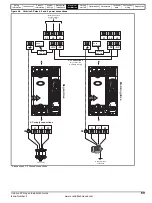
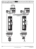
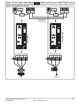
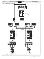
The following diagram shows the required connections for the SPMC to
T.84 and T.85. Also shown is the status relay which can be utilised if
required.
Figure 6-17 Parallel rectifier control terminals and descriptions
Unidrive SPMC/U external 24V supply requirements
Nominal voltage:
24V
Minimum voltage:
23V
Maximum voltage:
28V
Current drawn:
3A
Minimum start-up voltage:
18V
Recommended power supply: 24V, 100W, 4.5A
Recommended fuse:
4A fast blow (I
2
t <20A
2
s)
Figure 6-16 Single rectifier control terminals and descriptions
75
74
Fan control
0V common
Single Rectifier
73
72
Status input 0
0V common
71
Status input 1
0V common
85
84
External 24V supply
0V common
83
82
Status output 0
0V common
81
80
Status output 1
0V common
60
61
62
63
Inverter (master)
SPMA / SPMD
Status 0 input
0V common
Status 1 input
0V common
70
91
90
Status relay
75
74
Fan control
0V common
Rectifier 2
73
72
Status input 0
0V common
71
Status input 1
0V common
85
84
External 24V supply
0V common
83
82
Status output 0
0V common
81
80
Status output 1
0V common
60
61
62
63
Inverter (master)
SPMA / SPMD
Status 0 input
0V common
Status 1 input
0V common
70
91
90
Status relay
75
74
Fan control
0V common
Rectifier 1
73
72
Status input 0
0V common
71
Status input 1
0V common
85
84
External 24V supply
0V common
83
82
Status output 0
0V common
81
80
Status output 1
0V common
70
91
90
Status relay
Содержание SP1201
Страница 219: ......
Страница 220: ...0471 0029 02 ...

