Safety
Information
Introduction
Product
information
System
design
Mechanical
installation
Electrical
installation
Getting
started
Optimisation
Parameters
Technical
data
Component
sizing
Diagnostics
170
Unidrive SP Regen Installation Guide
www.controltechniques.com Issue Number: 2
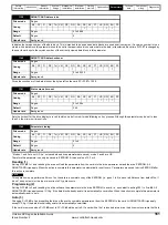
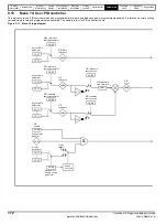
A loss of resolution can be seen when routing parameter values through the variable selectors due to the maximum available resolution being two
decimal places. The variable select output is scaled to ensure a 100.00% output gives full scale output to the destination parameter. This results in the
destination parameter jumping in steps equivalent to 0.01% resolution if the destination parameter has a greater resolution than two decimal places.
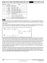
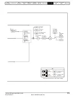
Sectional control
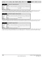
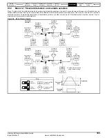
The sectional control function is intended to apply scaling and a speed offset to a 16 bit position value to generate a new 16 bit position value. The
output can be used as an input to the position controller (menu 13) or to generate an encoder simulation output via the SM-Universal encoder plus
module. This function can be selected for either variable selector, but the description below relates to variable selector 1.
The position input can be derived from any parameter, however it is intended to be used with a position value that has a range from 0 to 65535. The
input is scaled so that so that as Pr
12.13
is varied between -4.000 and 4.000 the proportion of the input position change added to the accumulator
varies from 0.000 to 2.000 (i.e. the change of position input value is added without scaling if Pr
12.13
is 0.000). The remainder from the scaling
division is stored and then added at the next sample to maintain an exact ratio between the position input and the position output, provided the speed
input is zero. The controller only takes the change of position from the input source parameter, and not the absolute value, so that when the controller
is first made active the output does not jump to the source position, but only moves with any changes of source position after that point in time.
The range of the output of the accumulator is 0.00% and 100.00%. Unlike other functions the value is not simply limited, but rolls under or over
respectively. Although the output destination can be any parameter it is intended to be used with a position value that has a range from 0 to 65535.
The speed input defines a speed offset with a resolution of 0.1rpm. Full scale of the source parameter corresponds to 1000.0rpm. Scaling may be
applied using Pr
12.14
to give a full scale value of 4000.0rpm. The speed input is added to the accumulator to move the output position forwards or
backwards with respect to the position input.
This sample time for this function is 4ms x number of menu 9 and 12 functions active. Extending the sample time does not cause any overflow errors
within the function, however, care must be taken to ensure that the input or output positions do not change by more than half a revolution within the
sample time, i.e for a sample time of 4ms the input or output speed should not exceed 7500rpm, for a sample time of 8ms the speed should not
exceed 3750rpm, etc. If the output of this function is to supply a reference to the position controller in menu 13 it must be the only user function in
menu 9 or 12 enabled.
If another function is enabled the input to the position controller will only change every 8ms (i.e. every 2 samples of
the position controller) and the speed reference applied to the drive could be very noisy.
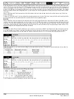
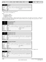
Mode value
Action
Result
0
Select input 1
output = input1
1
Select input 2
output = input2
2
Add
output = input2
3
Subtract
output = input1 - input 2
4
Multiply
output = (input1 x input2) / 100.0
5
Divide
output = (input1 x 100.0) / input2
6
Time constant
output = input1 / ((control param)s + 1)
7
Linear ramp
output = input1 via a ramp with a ramp time of (control
param) seconds from 0 to 100%
8
Modulus
output = | input1 |
9
Powers
control = 0.02: output = input1
2
/ 100.0
control = 0.03: output = input1
3
/ 100.0
2
control has any other value: output = input1
10
Sectional control
control = 0.00: disabled, accumulator reset and output
zero control <> 0.00: output as defined below
NOTE
%
4.000 + 12.13
4.000
12.14
Σ
Position
input
Position
output
Speed
input
d/dt
Accumulator
Содержание SP1201
Страница 219: ......
Страница 220: ...0471 0029 02 ...

