Safety
Information
Introduction
Product
information
System
design
Mechanical
installation
Electrical
installation
Getting
started
Optimisation
Parameters
Technical
data
Component
sizing
Diagnostics
82
Unidrive SP Regen Installation Guide
www.controltechniques.com Issue Number: 2
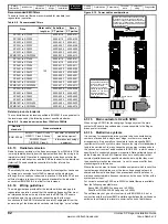
Recommended EMC filters
These are the same filters as recommended for standard (non-
regenerative) operation:
Table 6-8 Recommended filters
Related product standards
The conducted emission levels specified in EN50081-2 are equivalent to
the levels required by the following product specific standards:
Table 6-9 Conducted emission from 150kHz to 30MHz
6.5.13 Radiated emission
Radio frequency emission in the frequency range from 30MHz to 1GHz
is mainly radiated directly from the equipment and from the wiring in its
immediate vicinity. Operation in regenerative mode does not alter the
radiated emission behaviour, and the EMC data sheet for the individual
Unidrive SPs used should be consulted for further information.
N
Theoretically the use of two drives physically close together can cause
an increase in emission level of 3dB compared with a single drive,
although this is usually not observed in practice. All Unidrive SPs have
sufficient margin in respect of the generic standard for the industrial
environment
EN61000-6-4
to allow for this increase.
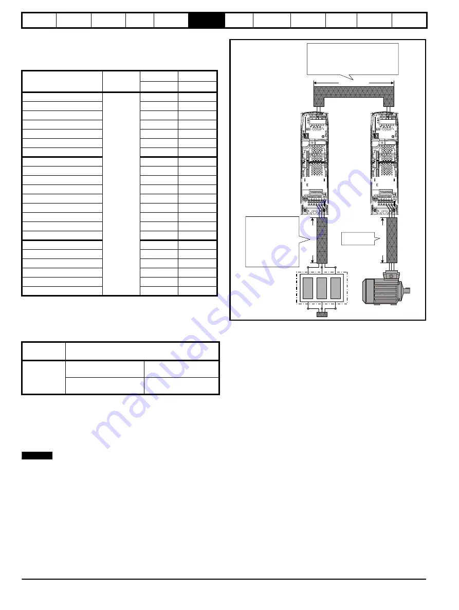
6.5.14 Wiring guidelines
The wiring guidelines provided for the individual drives also apply to
regenerative operation, except that the switching frequency filter must
be interposed between the input drive and the EMC filter. The same
principles apply, the most important aspect being that the input
connections to the EMC filter should be carefully segregated from the
power wiring of the drives which carries a relatively high “noise” voltage.
Figure 6-15 Power cable considerations
6.5.15 Main contactors K2 with SPMC
When using an SPMC for the charging of a regen system the main
contactor K2 should be positioned as close as possible to the Regen
drives power terminals.
6.5.16 Multi-drive systems
It is common for regenerative drive systems to be constructed using
numbers of drives with a single input stage, or other more complex
arrangements. It is generally not possible to lay down specific EMC
requirements for such systems, since they are too large for standardised
tests to be carried out. In many cases the environment corresponds to
the “second environment” as described in IEC61800-3, in which case no
specific limit to conducted emission is required. National legislation such
as the European Union EMC Directive does not usually require that
complex installations meet specific standards, but only that they meet
the essential protection requirements, i.e. not to cause or suffer from
electromagnetic interference.
Where the environment is known to include equipment which is sensitive
to electromagnetic disturbance, or the low voltage supply network is
shared with domestic dwellings, then precautions should be taken to
minimise conducted radio frequency emission by the use of a filter at the
system power input.
For currents exceeding 300A up to 2500A suitable filters are available
from the following manufacturers:
Epcos B84143-B250-5xx (range up to 2500A)
Schaffner FN3359-300-99 (range up to 2400A)
These filters may not give strict conformity with EN61000-6-4, but in
conjunction with the relevant EMC installation guidelines they will reduce
emission to sufficiently low levels to minimise the risk of disturbance.
Drive
Motor cable
length m
Schaffner
Epcos
CT part no. CT part no.
SP1201 to SP1202
100
4200-6118
4200-6121
SP1203 to SP1204
4200-6119
4200-6120
SP2201 to SP2203
4200-6210
4200-6211
SP3201 to SP3202
4200-6307
4200-6306
SP4201 to SP4203
4200-6406
4200-6405
SP5201 to SP5202
4200-6503
4200-6501
SPMD1201 to SPMD1204
4200-6315
4200-6313
SP1401 to SP1404
4200-6118
4200-6121
SP1405 to SP1406
4200-6119
4200-6120
SP2401 to SP2404
4200-6210
4200-6211
SP3401 to SP3403
4200-6305
4200-6306
SP4401 to SP4403
4200-6406
4200-6405
SP5401 to SP5402
4200-6503
4200-6501
SP6401 to SP6402
4200-6603
4200-6601
SPMA1401 to SPMA1402
4200-6603
4200-6601
SPMD1401 to SPMD1404
4200-6315
4200-6313
SP3501 to SP3507
4200-6309
4200-6308
SP4601 to SP4606
4200-6408
4200-6407
SP5601 to SP5602
4200-6504
4200-6502
SP6601 to SP6602
4200-6604
4200-6602
SPMA1601 to SPMA1602
4200-6604
4200-6602
SPMD1601 to SPMD1604
4200-6316
4200-6314
Generic
standard
Product standard
EN61000-6-4
EN55011 Class A Group 1
CISPR 11 Class A Group 1
Industrial, scientific and
medical equipment
EN55022 Class A
CISPR 22 Class A
Information technology
equipment
NOTE
±
DC bus connections
Regen drive
Motoring drive
Regen inductor
Motor
Cable length B
Ca
b
le len
g
th
A
Ca
b
le len
g
th
C
The DC connection between the Regen and
motoring drive carries common mode high
frequency voltage comparable with the output
voltage from a standard drive. Clearances and
recommendations for standard power cables
must be applied here.
The voltage present in the
wiring between the Regen
drive and regen inductor
is a source of radio
emission. These cables
should be kept as short as
possible. (I.e. The regen
inductor mounted as
close as possible to the
Regen drive.)
Standard wiring
practices apply.
Содержание SP1201
Страница 219: ......
Страница 220: ...0471 0029 02 ...


