


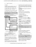


76 Chapter 5 Parameters
EV1000 Series General Purpose Variable Speed Drive User Manual
FH.10 Motor stabilization
fator
Range: 0
~
255
【
Depending on model
】
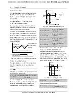
FH.10 is used to suppress the oscillation caused
by the drive and the motor. If the drive’s output
current changes constantly at fixed load, the
oscillation can be reduced by adjusting FH.10.
FH.11
~
FH.21 Reserved
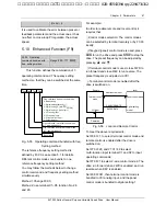
5.14 Protection (FL)
FL.00 Motor overload
protection mode
Range: 0
、
1
、
2
【
1
】
0: disabled
The overload protection is disabled. Be careful to
use this function because the drive will not protect
the motor in case of overload;
1:Common motor (with low speed compensation)
Since cooling conditions of common motor
deteriorates at low speed, the motor’s thermal
protection threshold should also be adjusted. The
“Low Speed” here refers to the operating
frequency lower than 30Hz.
2: Variable frequency motor (without low speed
compensation)
The cooling effect of variable frequency motor is
not affected by the motor’s speed, so low speed
compensation is not necessary.
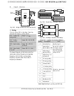
FL.01 Motor overload
protection factor
Range: 20.0
~
110.0
%【
100.0
%】
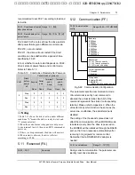
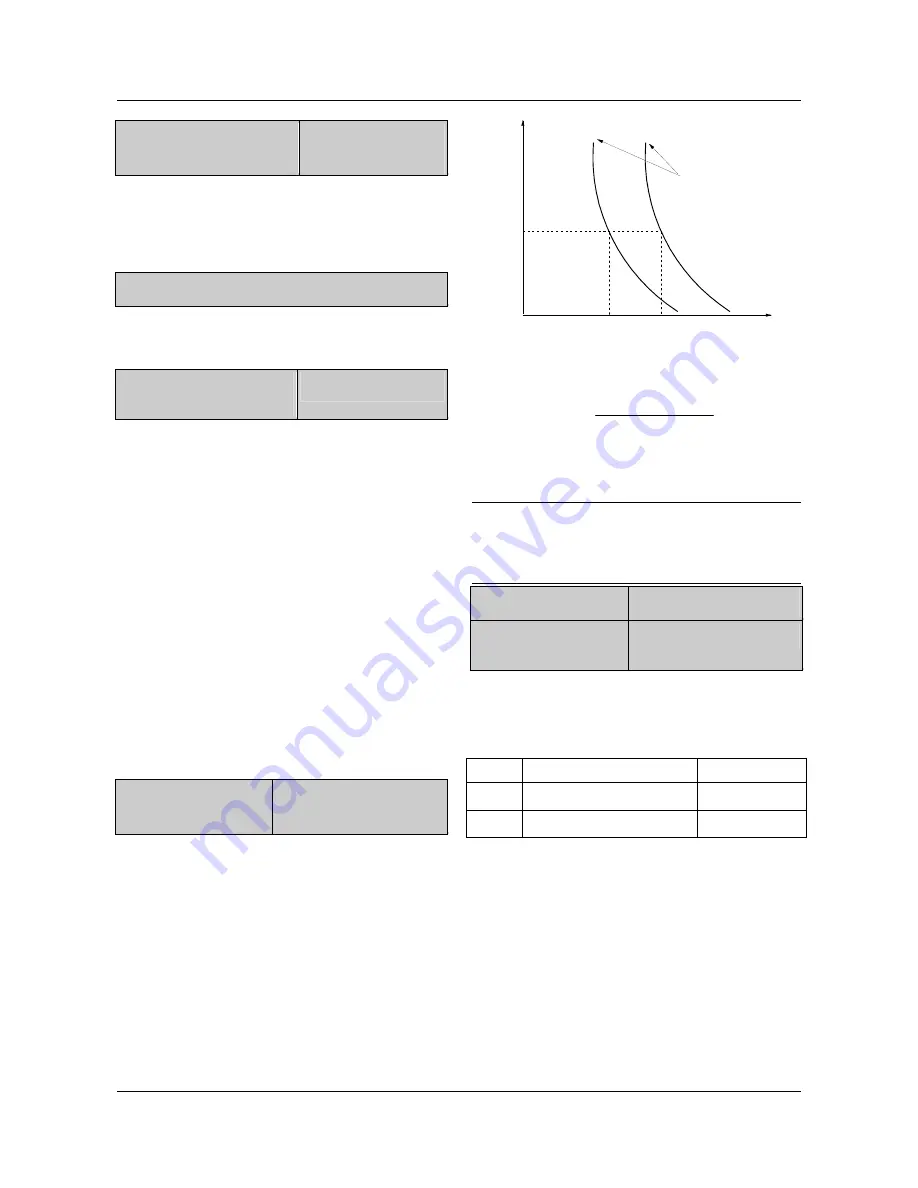
In order to apply effective overload protection to
different kinds of motors, the Max output current
of the drive should be adjusted as shown in Fig.
5-70.
Motor overload
protective
coefficient
100%
80%
1min
Time
Current
200%
160%
Fig. 5-70 Motor’s overload protection coefficient
The efficient is calculated by the formula below:
Motor overload
protection coefficient
motor rated current
inverter's rated output current
×
100
%
=
Generally, the Max load current is the motor’s
rated current.
Note
:
If the motor’s rated current does not match that of the
drive, adjust FL.00~FL.01 to perform overload
protection.
FL.02 Stall overvoltage Range: 0, 1
【
1
】
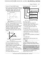
FL.03 Stall overvoltage
point
Range:Depending on model
FL.02=0, function disabled
FL.02=1, enabled
The setting of FL.03 is given in the table below:
Model
Range Default
380V 120.0%~150.0%
140.0%
220V 110.0%~130.0%
120.0%
When the drive is decelerating, the motor’s
decreasing rate may be lower than that of the
drive’s output frequency due to the inertia of load.
At this time, the motor will feed the energy back to
the drive, resulting in voltage rise on the drive's
DC bus, which will cause overvoltage trip.
Function of FL.02: during the deceleration, the
drive detects the bus voltage and compares it with
the stall over voltage point defined by FL.03. If the
bus voltage exceeds FL.03, the drive will stop
艾默生变频器、艾默生CT高级授权代理商--广州盟雄 020-85543394 qq:2294731312


