


Chapter 5 Parameters 59
EV1000 Series General Purpose Variable Speed Drive User Manual
zero.
40: Clear the setting of auxiliary reference
frequency
This function is valid for auxiliary reference
frequency (F9.01=1, 2 and 3) to clear it to zero, so
that the reference frequency is determined solely
by main reference.
41: Reset PLC state
When the drive stops in PLC mode, the
memorized PLC operating information (operating
stage, operating time, operating frequency, etc.)
will be cleared.
42: clear the counter to zero
This function is to clear the counter to zero and is
used in conjunction with function 43.
43: Input signal to trigger the counter
When the setting is 43, this terminal is used to
input counting pulse signal to the internal counter
of the drive. The max. pulse frequency is 200Hz.
The present counting value can be saved at
power off. See F7.33 and F7.34 for details.
44: input the signal of length
This function is only effective to multi-function
input terminals X4 and X5. The
terminal is used in
fixed-length control. Length is calculated by input
pulses. See F9.14~F9.19 for details.
45: pulse frequency input
This function is effective only to multi-function
input terminals X4 and X5. The terminal is used to
input pulse signal that is used as frequency
reference. Refer tp F1 parameters for the
relationship between input pulse frequency and
the reference frequency.
46: Single-phase speed measuring input
This function is effective only to multi-function
input terminals X4 and X5. See section 3.2.3 for
input characteristics. The speed control accuracy
is
±
0.1%. Single-phase speed feedback control
can be realized by using this terminal and PG.
47: Speed measuring input SM1
48: Speed measuring input SM2
This function is effective only to multi-function
input terminals X4 and X5. See section 3.2.3 for
input characteristics. The speed control accuracy
is
±
0.1%. 2-phase speed feedback control can
be realized by using this terminal and PG.
Note
:
When the drive is in motor auto-tuning status, No.
44~47 functions of X4 are disabled automatically.
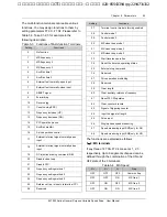
F7.08 FWD/REV operating
modes setup
Range: 0
~
3
【
0
】
This parameter defines four operating modes
controlled by external terminals.
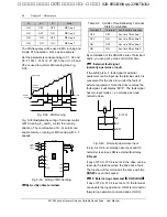
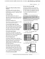
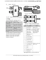
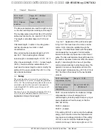
0: 2-wire operating mode 1
0
0
Run forward
Run reverse
Stop
K
1
FWD
COM
REV
EV1000
.
.
.
PLC
P24
.
.
K
2
K
2
K
1
0
1
0
1
1
1
Command
Stop
.
.
.
.
.
Fig. 5-41 2-wire operating mode 1
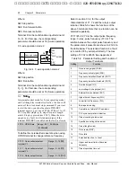
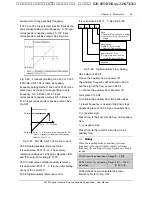
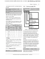
1:
2-wire operating mode 2
0
0
Run forward
Stop
Stop
K
1
COM
.
.
.
PLC
P24
.
.
K
2
K
2
K
1
0
1
0
1
1
1
0
0
Running command
Run reverse
FWD
REV
EV1000
.
.
.
.
.
0
1
Fig. 5-42 2-wire operating mode 2
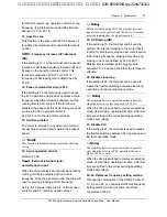
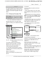
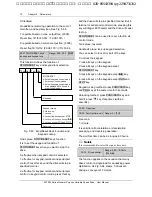
2: 3-wire operating mode 1
FWD
Xi
REV
SB3
COM
SB1
SB2
EV1000
.
.
.
.
PLC
P24
.
.
Fig. 5-43 3-wire operating mode 1
艾默生变频器、艾默生CT高级授权代理商--广州盟雄 020-85543394 qq:2294731312


