


62 Chapter 5 Parameters
EV1000 Series General Purpose Variable Speed Drive User Manual
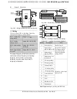
15: drive ready (RDY)
The RDY signal is output when the drive has no
fault, its DC bus voltage is normal, the Start
Prohibit function is disabled. It is ready to start.
16:Drive fails
The signal is given if the drive has faults.
17: Extended function 1 of host
The output signal of terminal Y1, Y2 or TC is
directly controlled by a serial port. Refer to the
communication protocol of EV1000.
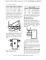
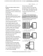
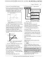
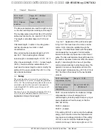
18:Upper and lower limits of traverse frequency.
The signal will be given if the range of traverse
frequency calculated based on central frequency
is higher than upper limit of frequency (F0.12) or
lower than the lower limit of frequency (F0.13), as
shown in Fig.5-45.
Before limiting amplitude
Upper limit of freq
Lower limit of freq.
T
raverse
operation
Y1: upper and lower limit
of traverse operation
After limiting amplitude
Central freq.
Fig. 5-45 Limiting the Amplitude of Traverse
19: preset operating time out
The signal is given if the drive’s total operating
time (Fn.01) reaches preset operating time
(Fn.00).
Note
:
When F7.04 is set at 44
~
46, the pulse output function
of Y2 is disabled automatically.
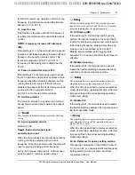
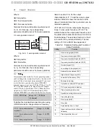
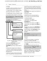
F7.13 Freq. arrival detection
range (FAR)
Range: 0.00
~
650.00Hz
【
2.50Hz
】
As shown in Fig. 5-46, if the drive’s output
frequency is within the detecting range of preset
frequency, a pulse signal will be output. It is
complementary to No.1 function in Table 9-1.
detecting range
Time
Time
Y
Preset
freq.
Output
Fig. 5-46 Freq. Arrival Signal Output
F7.14 FDT1 level
Range: 0.00
~
650.00Hz
【
50.00Hz
】
F7.15 FDT1 lag
Range: 0.00
~
650.00Hz
【
1.00Hz
】
F7.16 FDT2 level
Range: 0.00
~
650.00Hz
【
25.00Hz
】
F7.17 FDT2 lag
Range: 0.00
~
650.00Hz
【
1.00Hz
】
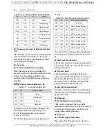
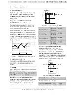
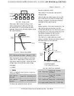
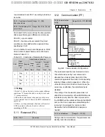
F7.14~F7.15 is a complement to the No.2
function in Table 5-9. F7.16~F7.17 is a
complement to the No.3 function in Table 5-9.
Their functions are same. Take F7.14~F7.15 for
example: when the drive’s output frequency
reaches FDT1 level, it outputs an indicating signal
until its output frequency drops below FDT1 level
(FDT1 level-FDT1 lag). As shown in Fig. 5-47.
FDT1 lag
Time
Time
Y
FDT1 level
Output
frequency
Fig. 5-47 Frequency Detection
F7.18
~
F7.25
Reserved
These parameters are not used.
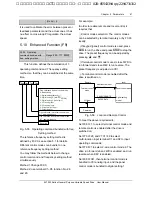
F7.26 AO1 output function
Range: 0
~
12
【
0
】
艾默生变频器、艾默生CT高级授权代理商--广州盟雄 020-85543394 qq:2294731312


