


_________________________________________________________________________________
_________________________________________________________________________________
Universal Network Terminal TAU-32M.IP 305
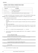
APPENDIX D. EXAMPLE OF SWITCH CONFIGURATION USING VLAN
Objective:
Tagged traffic comes to the switch port 0 with the following tags: 101, 102 and 103. Packets with
VLAN ID=101 should be sent untagged to the port 1, packets with VLAN ID=102 should be sent untagged to the port
2. VLAN 103 is proposed to be used for telephony and device management, i.e. packets with VLAN ID=103 should be
sent untagged to the switch CPU port.
1.
Using Ethernet cable, connect gateway Ethernet port to your local area network. Connect to the device using
WEB configurator.
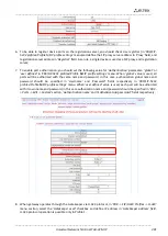
2.
Define the packet routing rules—
'802.1q'
—in
'Switch -> 802.1q'
submenu.
For VLAN 101, port 0 is tagged, port 1 is untagged, other ports are not members of this VLAN.
For VLAN 102, port 0 is tagged, port 2 is untagged, other ports are not members of this VLAN.
For VLAN 103, port 0 is tagged, CPU port is untagged, other ports are not members of this VLAN.
3.
For switch ports, you should configure '802.1q' operation mode in 'Switch -> Switch ports settings' submenu,
i.e. 'IEEE Mode = Secure'. For untagged traffic coming to ports 1, 2 and CPU to be transferred to port 0
tagged, you should configure the respective
'Default VLAN ID'
tags—101, 102 and 103—for ports 1, 2 and
CPU. Also, select 'Enable VLAN' checkboxes for these ports, including port 0, that allow to use
'Default VLAN
ID'
settings.