background image

PURELAB Classic 

Operator Manual 

ELGA 

Page 8


PURELAB Classic

 Version 2 11/15 

Classic UVF 


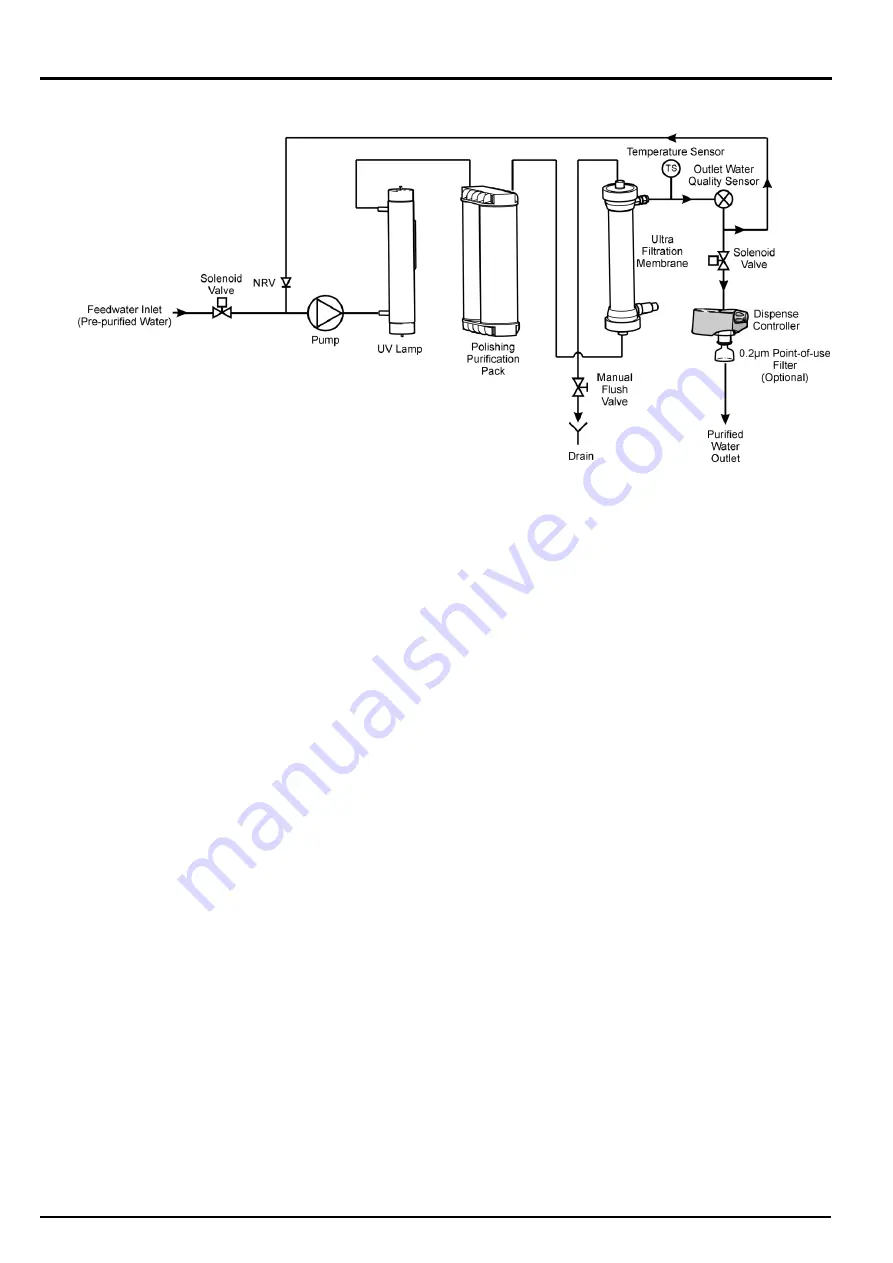
Pre-treated  water  enters  via  an  inlet  solenoid  and  is  then 
pumped  through  the  UV  chamber,  a  purification  pack,  an 
ultrafilter  and  temperature  and  water  quality  sensors  before 
being  dispensed  or  re-circulated  through  a  non-return  valve 
back to the pump inlet. 

Purified water flows directly through the UV chamber where it 
is exposed to intense UV radiation at a wavelength of 185 nm 
to  provide  continuous  bacterial  control  and  the  photo-
oxidation of residual organic impurities.  

Ionic  and  organic  impurities  are  removed  by  the  purification 
pack;  the  ultrafilter  removes  pyrogens,  bacteria  and  other 
microbial  impurities  as  well  as  particles.  Product  water 
resistivity  and  temperature  are  measured  before  dispense 
and  will  indicate  when  the  purification  pack  needs  to  be 
replaced. 

The  water  within  the  unit  is  re-circulated  through  the 
purification  technologies  to  maintain  purity.  To  reduce  heat 
build up the recirculation is at reduced flow rate and is set to 
be intermittent (5 minutes every hour). 

An  optional  POU  filter  is  available  if  required  to  protect  the 
outlet from bacterial contamination. 

Содержание PURELAB Classic - US

Страница 1: ...PURELAB Classic US Operator Manual...

Страница 2: ......

Страница 3: ...copyright and all restrictions on reproduction and use apply to all media in which this information may be placed VWS UK Ltd pursue a policy of continual product improvement and reserve the right to...

Страница 4: ...2 Positioning the PURELAB Classic 13 5 3 Connecting the PURELAB Classic 15 5 4 Initial Controller Set up 17 5 5 Setting Up Password Resetting Replacement Timers 21 5 6 Initial Start Up 23 5 7 POU Fil...

Страница 5: ...Manual PURELAB Classic US Version 2 11 15 Page iii 11 KEY TO CONTROL PANEL 43 11 1 Icons 43 11 2 Alarm Conditions 44 11 3 Replacement Timers 44 11 4 Quality Alarms 45 12 WARRANTY CONDITIONS OF SALE 46...

Страница 6: ...2 Use of this Manual This manual contains full details on installation commissioning and operation of the PURELAB Classic unit If the instructions in this handbook are not followed then the performan...

Страница 7: ...he ON OFF switch is located at the left hand side of the unit The mains power lead is located just behind the ON OFF switch WARNING THIS APPLIANCE MUST BE EARTHED The main water supply should be isola...

Страница 8: ...ti purpose disinfecting tablet is used and relevant safety information is included in this handbook Please refer to the manufacturer for material safety data sheets EfferSan is EPA registered as Multi...

Страница 9: ...to complement the unit see Section 10 Consumables and Accessories for details Control Panel Dispense Nozzle Dispense Controller Door PURELAB Classic The PURELAB Classic range of water purification un...

Страница 10: ...ump inlet Ionic and organic impurities are removed by the purification pack Product water resistivity and temperature are measured before dispense and will indicate when the purification pack needs to...

Страница 11: ...ntense UV radiation at a wavelength of 185 nm to provide continuous bacterial control Ionic and organic impurities are removed by the purification pack Product water resistivity and temperature are me...

Страница 12: ...by the purification pack the ultrafilter removes pyrogens bacteria and other microbial impurities as well as particles Product water resistivity and temperature are measured before dispense and will i...

Страница 13: ...s bacterial control and the photo oxidation of residual organic impurities Ionic and organic impurities are removed by the purification pack the ultrafilter removes pyrogens bacteria and other microbi...

Страница 14: ...max Carbon Dioxide 30 ppm max Silica 2 ppm max Particulates Filtration down to 0 2 micron advisable to protect internal and or point of use filters Temperature 1 40 C Recommended 10 15 C Flowrate maxi...

Страница 15: ...cm or S cm Water quality alarm Selectable alarm setpoints Date time Adjustable Auto restart after power failure Selectable On Off Audible alarm Selectable On Off Temperature control Selectable alarm s...

Страница 16: ...ied Water Specification DI UV UF UVF Flowrate 2 0 l min max Inorganic Resistivity 18 2 M cm 0 055 S cm TOC 15 ppb 5 ppb 15 ppb 10 ppb Bacteria 1 cfu ml 1 cfu ml 1 cfu ml 1 cfu ml Pyrogens 0 02 Eu ml 0...

Страница 17: ...rpose control buttons Details of how to use the controls will be given in the appropriate sections The PURELAB Classic control panel has a range of control icons as follows Button Icon Function PROCES...

Страница 18: ...l mounted against a vertical wall capable of supporting the weight for this we recommend the use of the wall mounting kit Part No LA610 on substantial brick concrete walls or LA622 for stud partition...

Страница 19: ...potable water pre purified using reverse osmosis deionisation or distillation If using a supply other than reverse osmosis treated it is strongly recommended that a 0 2 micron membrane filter is inst...

Страница 20: ...tube 4 PUSH tube into connector Step 2 Connect Water Inlet 1 Connect 8 mm tube from the PURELAB Classic inlet to the inlet strainer 2 Connect the inlet strainer to the pre purified water supply Step...

Страница 21: ...into mains socket Step 5 Reservoir Level Connection 1 INSERT jack plugs into the level control socket located at rear of unit and reservoir Note If wall mounting the unit it is recommended that the j...

Страница 22: ...ving the by pass block in place of DI pack press the PROCESS button to return to the initial power up screen 2 PRESS MENU button to activate the set up menu sequence A series of set up screens will no...

Страница 23: ...nstigate change reminders it will appear on printed records 1 PRESS Dispense Controller A cursor will appear under day 2 ROTATE Dispense Controller to increase or decrease day 3 PRESS Dispense Control...

Страница 24: ...e on going display of uncompensated values is generally not recommended as it can lead to confusion among users and increase the possibilities of dispensing water of inadequate purity Step 8 Product W...

Страница 25: ...cs visibility 1 ROTATE Dispense Controller slowly to adjust viewing angle 2 PRESS TICK button Step 11 Auto Restart This allows the selection of the AUTO MANUAL restart option If auto restart is select...

Страница 26: ...once 3 ROTATE Dispense Controller to enter new password 4 PRESS TICK button to accept new password Step 3 Purification Pack Replacement Date The replacement date for Purification Packs is automatical...

Страница 27: ...ate if fitted 1 PRESS RESET button to reset the Filter Replacement Date OR PRESS TICK button to accept Replacement Date and proceed to Sanitization Reminder 2 PRESS TICK button to confirm that resetti...

Страница 28: ...onnect a temporary tube from the dispense outlet to a suitable drain or sink 2 SWITCH ON electrical supply 3 Press the dispense controller The unit will automatically go into a rinse procedure 36 mins...

Страница 29: ...2 PRESS TICK button to accept the Purification Pack 3 PRESS TICK button to calculate replacement date Step 7 Final Rinse Air Bleed 1 PRESS PROCESS button and ALLOW the process screen to appear 2 PRESS...

Страница 30: ...d to achieve additional laboratory specific application requirements Step 1 POU Filter Installation 1 LOCATE the fixed dispense point and UNSCREW the nozzle 2 ENSURE O ring seal is still properly loca...

Страница 31: ...dispense the unit will continue to recirculate for a short period before returning to the intermittent routine CAUTION If the PROCESS button is double clicked the unit will switch off To maintain wat...

Страница 32: ...anging If the system is being e commissioned or sanitized after an extended period during which it was not used If the pack has exceeded 12 months use as indicated by the consumable reminder alarm Ste...

Страница 33: ...circumstances If indicated by the consumable reminder alarm When low pyrogen levels can no longer be maintained When the required flow rate can no longer be maintained Step 1 Switch Unit Off 1 SWITCH...

Страница 34: ...and bottom brown caps and discard Step 6 Fit New UF 1 REFIT top and bottom connectors to new UF ensuring the O rings are correctly located at each end 2 RECONNECT quick connect coupling CAUTION Ensure...

Страница 35: ...or sink 4 OPEN the flush valve and press the dispense knob the system will begin its flush sequence 5 After approximately 3 minutes countdown is indicated on the display the unit will sound a buzzer...

Страница 36: ...hite lamp holder fitted to the bottom of the UV unit CAUTION Hold on to the pins on the lamp in case it falls out and breaks Step 3 Remove Lamp Plates LC170 1 UNDO screws in plate at top 2 REMOVE plat...

Страница 37: ...se Filter LC134 Step 1 Remove POU Filter 1 UNSCREW the old filter from the fixed dispenser and discard 2 ENSURE O ring seal is still properly located 3 RINSE connection with IPA or ethanol Dispense wa...

Страница 38: ...bing 5 REMOVE the inlet strainer from its position Step 2 Dismantle the Inlet Strainer 1 HOLD inlet strainer over a sink or receptacle 2 UNSCREW inlet strainer 3 REMOVE mesh filter 4 CHECK mesh filter...

Страница 39: ...If the product water is used for particularly stringent applications Step 1 Start Sanitization Cycle 1 ENSURE unit is ready to use 2 SWITCH OFF electrical supply 3 REMOVE POU filter if fitted 4 OPEN...

Страница 40: ...spense to drain for 3 minutes countdown indicated on the display the unit will then sound a buzzer and stop The UF flush valve close icon will appear indicating the manual UF flush valve should be clo...

Страница 41: ...3 CLOSE front door Step 7 Return to Normal Operation 1 PRESS PROCESS button twice The unit has now been sanitized but should be allowed to rinse to a suitable quality For particularly sensitive appli...

Страница 42: ...y duty plastic bag Do not return to original container Wash away any residues with copious amounts of water Toxicity Serious risk of poisoning by inhalation or ingestion Irritating to skin eyes and re...

Страница 43: ...s used for particularly stringent applications Step 1 Start Sanitization Cycle 1 ENSURE unit is ready to use 2 SWITCH OFF electrical supply 3 REMOVE POU filter if fitted 4 OPEN the door Step 3 Add Min...

Страница 44: ...for the remainder of the time and then automatically proceed to the rinse procedure The unit will alternate between a rinse to drain and recirculate for a total of 44 minutes Upon completion the alarm...

Страница 45: ...litate a quicker system recovery it is suggested to dispense a volume of approximately 10 litres Note Once a sanitization cycle has commenced the PURELAB Classic cannot be used to purify water until t...

Страница 46: ...ct alarm point is set See Section 5 4 Step 10 Temperature Alarm Setting Check feedwater temperature has not risen suddenly Dispense some water to allow cold water to be drawn into the unit Purificatio...

Страница 47: ...taken to order the correct consumable items Required for reservoirs LA611 LA612 LA613 LA620 Accessory Cat No Installation kit LA642 Pressure regulator valve feedwater pressures 0 7 bar 10 psi but 4 b...

Страница 48: ...Version 2 11 15 Page 43 11 KEY TO CONTROL PANEL 11 1 Icons Icon Description Mute Alarm Accept Scroll Auto Restart Manual Restart Set Up Menu Cursor Option Choice Cursor Selection Choice Cancel Reset...

Страница 49: ...ashing Purification Pack not in place Flashing Reinstall Purification Pack Flashing Clock stopped Flashing Reservoir Level Disconnect Fault Flashing Incorrect Password Flashing Open UF Flush Valve Fla...

Страница 50: ...ELGA PURELAB Classic Operator Manual PURELAB Classic Version 2 11 15 Page 45 11 4 Quality Alarms Screen Description Outlet Purity Alarm Temperature Alarm...

Страница 51: ...VWS UK Ltd promptly of any such defect The exclusive remedy provided herein shall not be deemed to have failed of its essential purpose so long as VWS UK Ltd is willing and able to repair or replace a...

Страница 52: ...customer from the use of its process systems Products or components manufactured by companies other than VWS UK Ltd or its affiliates Non VWS UK Ltd products are covered by the warranty if any extende...

Страница 53: ...44 0 0203 567 7300 Fax 44 0 0203 567 7205 E mail techsupport elgalabwater com For the address of your nearest ELGA LabWater Sales and Service office visit the country list on our website http www elg...

Отзывы: