


© ElektroPhysik
QuintSonic 7
87 von 184
Two very broad amplitudes are prominent: the amplitude of the second coupling echo (z) and that
of the interface echo (1). This is due to the unevenness of the wood surface (as compared to the
surface of a plastics base, for instance). The 3 mm diameter ultrasound beam hits the different
peaks and valleys of the wooden surface. The portions of reflection are received by the measuring
head at different instants of time to accumulate to the typical large pulse shape.
In addition, a very thick coupling layer can be observed, the traveling time in the coupling layer
being almost 40 ns. This is also caused by the unevenness of the wooden surface. During the
painting procedure, such differences in height will not be completely compensated that’s why the
unevenness of the wooden base will be transferred to the paint surface. The measuring head only
contacts the peaks of surface. The valleys are filled with couplant. If you add the pulse shape
enlargement of the coupling echo (Z), a couplant thickness larger than the actual one will result as
an average. You can also see from the A-scan image that the coupling index is not particularly
high. This indicates the coupling performance is not optimal. However, you have to accept, as the
situation cannot be changed.
Finally, a clear deviation of the base line from the zero line can be observed behind the interface
echo (1). This is due to the increased noise floor caused by the strong granularity of the wood. In
the above example, the clipping limit as set is high enough for noise floor suppression. If, however,
the noise floor should increase during further measurements, setting the upper clipping limit to 4%
can remedy. Another solution would be to define a blocked domain behind echo (1) or to set the
number of echoes to be evaluated to 1.
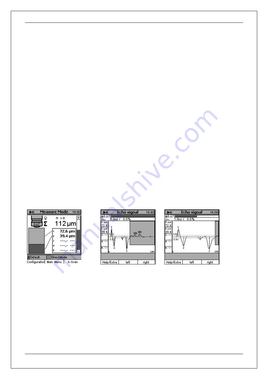
10.3 Two-layer paint on steel
X-Zoom = 1 X-Zoom = 2
Measuring range: 1 (300 ns).
Also in this example, the basic setting (for values see section 9.2) has been used. All expected
echoes have been extracted (1,2). Due to the small differences in the acoustic properties of layer
materials, however, the first interface echo is relatively small (-3.6%). To increase the processing
accuracy, it is recommended to reduce the negative clipping limit to
–2%, for instance.
The large negative echo (2) is typical for a transition from plastic to metal. Metals always exhibiting
a clearly higher acoustic impedance than plastics, the echo at the transitional layer will always be a
large negative one. For that reason, such interface layers can be easily identified.