Settings
EFORT INTELLIGENT EQUIPMENT CO.,LTD
86
Line9: The robot moves down to posture 2;
Line10: Wait to grab the workpiece;
Line11: The robot moves up to posture 3;
Line13: The end of the loop.
Note!
Because the hand eye calibration is performed on the robot, the
data results of three workpiece position, namely vision.x
,
vision.y
,
and vision.z, can be applied directly. However, vision.a,
vision.b, and vision.c need to be compensated numerically
according to the actual situation on site.
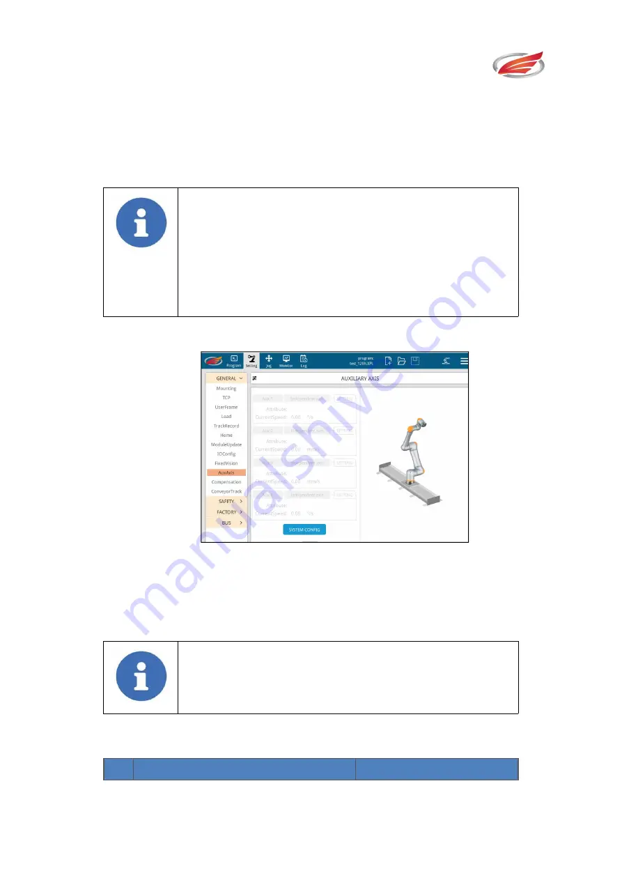
5.1.10 Auxiliary Axis
Fig.5-20 Auxiliary Axis Configuration Interface
Based on standard robot, the function of auxiliary axis is to add 1 to 4 auxiliary axes to
help the robot complete the complex site work of customers.
Note!
The current collaborative robot control system can support a
maximum of 4 auxiliary axes.
Auxiliary Axis System Configuration
Procedures of Setting Auxiliary Axis Parameter:
#
Demonstration
Remarks


