background image

18

Section VII - Service, Inspection & Maintenance 

A. Service Tools

No special tools are required to service this valve series.

B. Inspection

Periodic inspection of the fluid condition and tube or piping
connections can save time consuming breakdown and
unnecessary parts replacement. the following should be
checked regularly.

1. All hydraulic connections must be kept tight. A loose

connection in a pressure line will permit the fluid to leak
out. If the fluid level becomes so low as to uncover the
inlet pipe opening in the reservoir, extensive damage to
the system can result. Loose connections also permit air
to be drawn into the system resulting in a noisy and/or
erratic operation.

2. Clean fluid is the best insurance for long service life.

Therefore, check the reservoir periodically for dirt and
other contaminants. If the fluid becomes contaminated,
flush the entire system and add new fluid.

3. Filter elements should also be checked periodically. A

clogged filter element will cause higher pressure drops
within the system.

4. Air bubbles in the reservoir can ruin the valve and other

components. If bubbles are seen, locate the source of
the air and seal the leak.

C. Adding Fluid to the System

When hydraulic fluid is added to replenish the system, pour it
through a fine wire screen (200 mesh or finer). When
applicable, pump the fluid through a 10 micron filter. DO
NOT use a cloth to strain the fluid or lint may enter the
system.

D. Adjustments

No periodic adjustments are required other than normal
system maintenance,

E. Replacement Parts

Reliable operation throughout the specified operating range
is assured only if genuine Vickers parts are used.
Sophisticated design processes and material are used in the
manufacture of our parts. Substitutions may result in early
failure. Part numbers are shown in the parts and service
drawings listed in Table 1.

F. Product Life

The service life of this product is dependent upon
environment, duty cycle, operating parameters and system
cleanliness. Since these parameters vary from application to
application, the ultimate user must determine and establish
the periodic maintenance required to maximize life and
detect potential component failure.
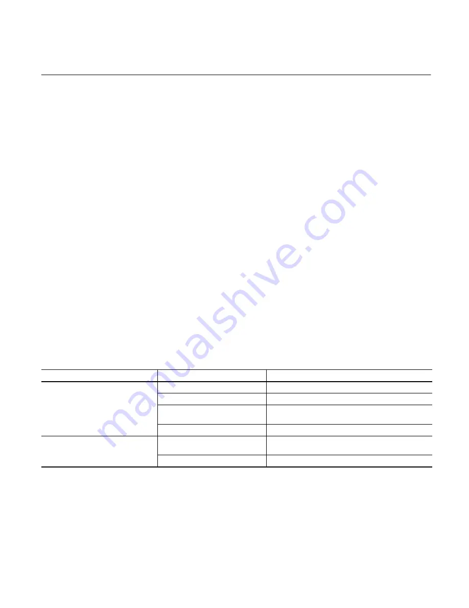
G. Troubleshooting

Table 4 lists the common difficulties experienced with
directional valves and systems. It also indicates the probable
causes and remedies for each of the troubles listed.

Also remember that many apparent failures may actually be
the failure of other parts of the system. The cause of
improper operation is best diagnosed with adequate testing
equipment and a thorough understanding of the complete
hydraulic system.

TROUBLE

PROBABLE CAUSE

REMEDY

Valve spool fails to move

Dirt in system

Disassemble, clean and flush.

Solenoids inoperative

Check electrical source and solenoids.

Improper assembly

Check proper assembly. Refer to appropriate figure
and assembly procedure.

Improper installation connections

Check installation drawings

Valve produces undesirable response

Improper valve assembly
Improper installation connections

Checks parts drawing and installation drawing for
proper assembly and installation connections

Solenoid wiring reversed

Reverse connections to the solenoids

Table 4. Troubleshooting Chart

Содержание VICKERS DG3V-10 A Series

Страница 1: ...5007 01 EN 1099 M DG3V 10 DG5V 10 Solenoid Pilot Operated Overhaul Manual VICKERS Directional Control Valves...

Страница 2: ...peration 7 Section IV Pilot Valve Section 13 Section V Internal Valve Functions 15 Section VI Installation 16 Section VII Service Inspection Maintenance 18 Section VIII Overhaul 19 DG5V 8 S H C 10 25...

Страница 3: ...contained in this manual The parts and installation drawings listed in Table 1 are available from any Vickers Distributor C Model Codes Variations within each basic model series are covered in the mod...

Страница 4: ...psi See spool spring combinations below Left Hand Build L A Models only omit if not required Fast Response X Not available with CETOP 3 pilots or pressure centered D and DB models Spool Control Modif...

Страница 5: ...els 2 7 If both are required available on A B C N models 2 8 If both are required available on AL B C N D models CAUTION Stroke adjust pilot pressure models are rated to a maximum of 210 bar 3000 psi...

Страница 6: ...ports are open or closed See Figure 1 Oil flow is directed from one port to another within the body and out of a port to the work C Two Stage Directional Valve Construction Two stage directional valv...

Страница 7: ...ked and the cylinder is held in a definite position In some circuits flow from the tank port is piped into the pressure port of another valve This allows the same source of power to operate two differ...

Страница 8: ...the center position A B P T Closed Center Bleed A B T A P B F Type 52 spool A B P T Closed Center Regen by Solenoid A T A P B G Type 521 spool A B P T Closed Center Regen by Solenoid B T A P B H Type...

Страница 9: ...ol can move from its last position under the influence of gravity or tank line pressure This must be considered during the design of the system Units with floating type spools have the model code lett...

Страница 10: ...to the sleeve and piston areas on the left side but the sleeve is bottomed against the valve body at this time Only the piston area applies force to the left end of the spool Since the spool land are...

Страница 11: ...t To limit the spool travel loosen the jam nut and turn adjusting screw clockwise Figure 8 Stroke Adjuster Feature 2 7 5 1 3 4 6 Main Stage Spool Part No Part Name 1 2 3 4 Cover Spring O Ring Back up...

Страница 12: ...Dowel Pin Figure 10 Reducer Module Table 2 Shift Response Times w CETOP 3 Pilot Fast Response option not available Valve Type Condition Pilot Pressure 10 bar 150 psi Pilot Pressure 100 bar 1500 psi P...

Страница 13: ...l position 3 Detents A detent mechanism is installed on one or both ends of the pilot valve spool Detent valve solenoids can be momentarily energized to the correct position and then power may be remo...

Страница 14: ...Solenoids DG4S4 01 pilot valves are usually equipped with air gap solenoids Air gap solenoids are isolated from system fluid and can be removed and replaced without disturbing the system A push pin a...

Страница 15: ...a D Brad Harrison Connectors Brad Harrison connectors thread into the 1 2 NPTF opening in the wiring housing of a DG4V 3 or a DG4S4 01 directional valve PA3 A prefix of PA3 in the model code indicates...

Страница 16: ...CAN overcome pilot pressure Drain connection Y is used for externally drained models Pressure centered D models use two drain connections Y and W All external drain connections MUST be piped directly...

Страница 17: ...he necessary fittings and connections required for proper installation 3 The number of bends in tubing should be kept to a minimum to prevent excessive turbulence and friction of fluid flow Tubing mus...

Страница 18: ...ntenance E Replacement Parts Reliable operation throughout the specified operating range is assured only if genuine Vickers parts are used Sophisticated design processes and material are used in the m...

Страница 19: ...Slight variations may be noted on your model depending on the type of accessories and unit design Figure 15 may be used for all models except pressure centered D models regardless of the design Refer...

Страница 20: ...emove four screws 3 and crossover plate from main stage body 6 3 Remove and discard two O rings 5 from crossover plate Note The following section pertains to main stage disassembly If your unit does n...

Страница 21: ...18 and O ring 19 from core tube S A 20 Discard O Ring 19 6 Remove pilot spool 21 from body 5 7 Remove plugs 24 and 22 and O Ring 23 from body 5 Discard O Ring 23 8 Secure the body and remove plugs 25...

Страница 22: ...voltage rating of the coil Refer to Table 8 This test is superficial but a more rigorous test requires special equipment If the coil seems to be burned or extreme heat is encountered during operation...

Страница 23: ...Make sure the spool moves freely inside the body bore and is oriented properly See parts drawing 7 Install piston 12 sleeve 11 and spring 10 into cover 8 8 Install O ring 9 in cover and install cover...

Страница 24: ...stop 16 spring 17 and push pin 18 on spool 21 4 Install O ring 19 on core tube S A 20 and install core tube S A into body 5 5 Install O ring 9 on core tube S A 20 6 Install gasket 14 and coil 10 on bo...

Страница 25: ...at 1 3 Pilot Choke 1 18 Poppet 1 4 Reducer 1 19 Spring 1 5 Body 1 20 Sleeve 1 6 O Ring 9 21 Plug 4 7 Screw 4 22 O Ring 11 8 Adapter Plate 1 23 Plug 10 9 Plug 1 24 O Ring 2 10 Screw 8 25 O Ring 4 11 Co...

Страница 26: ...5 O Ring 1 2 Name Plate 1 16 Screw 4 3 Screw 4 17 Cover 1 4 Cover Plate 1 18 O Ring 1 5 O Ring 2 19 Spring 1 6 Body 1 20 Washer 1 7 Screw 4 21 O Ring 2 8 Cover 1 22 O Ring 3 9 O Ring 1 23 Plug 13 10 S...

Страница 27: ...Nameplate 1 15 O Ring 2 3 Cover 1 16 O Ring 1 4 Gasket 1 17 Push Pin 1 5 Terminal Box 1 18 Spring 1 6 Gasket 1 19 Washer DC models 2 7 Screw 2 20 Washer AC models 2 8 Strap 1 21 Core Tube S A 1 9 Scr...

Страница 28: ...1 22 Plug 1 8 Knob 2 23 O Ring 1 9 O Ring 2 24 Plug 1 10 Coil Type A 2 25 Plug 1 11 DIN Coil 2 26 O Ring 1 12 Plug 2 27 Plug 1 13 DIN Receptacle 2 28 O Ring 1 14 Gasket 2 29 O Ring 5 15 Washer 2 Figu...

Отзывы: