iv
9395P 250 kVA / 275 kVA / 300 kVA
User’s and Installation Guide
List of Figures
2
. . . . . . . . . . . . . . . . . . . . . . . . . . . . . . . . . . . . . . . . .
3
13
14
14
15
15
23
26
27
29
Figure 1-1 .UPS (250 kVA / 275 kVA / 300 KVA) with the 7-inch color touchscreen
. . . . . . . . . . . . . . . . . . . . . . . . . . . . . . . . . . . . . . . . . . . . . . . . . . . . . . . . . . . . . . . . . . . . .
Figure 1-2 .Eaton 9395P UPS 250 kVA / 275 kVA / 300 kVA typical single-module system (including a battery cabinet
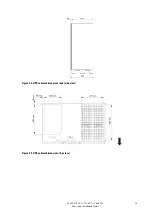
Figure 3-1 .UPS cabinet dimensions (front view) . . . . . . . . . . . . . . . . . . . . . . . . . . . . . . . . . . . . . . . . . . . . . . .
Figure 3-2 .UPS cabinet dimensions (right side view)
Figure 3-3 .UPS cabinet dimensions (top view)
. . . . . . . . . . . . . . . . . . . . . . . . . . . . . . . . . . . . . . . . . . . . . . . . . . . . . . . . . . . . . . . . . . . . . . . . . . . . . . . . . . . . . . . . . . . . . . .
Figure 3-4 .UPS cabinet dimensions (bottom view with mounting brackets)
. . . . . . . . . . . . . . . . . . . . . . . . . . . . . . . . . . . .
Figure 3-5 .REPO switch dimensions
Figure 3-6 .Eaton 9395P UPS 250 kVA / 275 kVA / 300 kVA cabinet as shipped on pallet
Figure 4-1 .Removing left side shipping bracket
Figure 4-2 .Removing right side shipping bracket . . . . . . . . . . . . . . . . . . . . . . . . . . . . . . . . . . . . . . . . . . . . . . .
Figure 4-3 .Typical Bus Bar Barrel Lug Mounting – Hardware Assembly
Figure 4-4 .Conduit and wire entry locations
31
Figure 4-5 .Distributed bypass wire
. . . . . . . . . . . . . . . . . . . . . . . . 32
33
34
35
36
36
38
38
40
42
42
43
45
45
46
47
49
50
50
54
55
57
57
58
59
61
63
64
66
67
. . . . . . . . . . . . . . . . . . . . . . . . . . . . . . . . . . . . . . . . . . . . . . . . .
69
70
72
73
74
76
Figure 4-6 .UPS power terminal locations–Common Rectifier Feed . . . . . . . . . . . . . . . . . . . . . . . . . . . . . . . . . . . . . . . .
Figure 4-7 .UPS power terminal detail AA– Common Rectifier
Feed .
. . . . . . . . . . . . . . . . . . . . . . . . . . . . . . . . . . . . . . . . . . . . . . . . . . . . . . . . . . . . . . . . . . . . . . . . . . . . . . .
Figure 4-8 .Interface terminal locations– Separate Rectifier Feed
Figure 4-9 .UPS Power Terminal Detail AA – Separate Rectifier
. . . . . . . . . . . . . . . . . . . . . . . . . . . . . . . . . . . . . . .
Figure 4-10 .UPM Rectifier Input Power Terminal Block Detail . . . . . . . . . . . . . . . . . . . . . . . . . . . . . . . . . . . . . . . . . .
Figure 4-11 .UPS Power Terminal Detail BB – Common Battery
Figure 4-12 .UPS Power Terminal Detail BB – Separate Battery
Figure 4-13 .Interface Terminal Locations . . . . . . . . . . . . . . . . . . . . . . . . . . . . . . . . . . . . . . . . . . . . . . . . . .
Figure 4-14 .Interface Terminal Detail
Figure 4-15 .Typical Alarm Relay Connection
Figure 4-16 .Terminal Blocks TB1, TB2, and TB3 Connector Assignments
Figure 4-17 .Typical Battery Interface Connection . . . . . . . . . . . . . . . . . . . . . . . . . . . . . . . . . . . . . . . . . . . . . . .
Figure 4-18 .Typical Battery Interface Connection – Separate Battery System
Figure 4-19 .X-Slot Communication Bays . . . . . . . . . . . . . . . . . . . . . . . . . . . . . . . . . . . . . . . . . . . . . . . . . .
Figure 4-20 .REPO switch . . . . . . . . . . . . . . . . . . . . . . . . . . . . . . . . . . . . . . . . . . . . . . . . . . . . . . . .
Figure 4-21 .Normally-Open REPO Switch Wiring . . . . . . . . . . . . . . . . . . . . . . . . . . . . . . . . . . . . . . . . . . . . . . .
Figure 4-22 .
. . . . . . . . . . . . . . . . . . . . . . . . . . . . . . . . . . . . . . . . . . . . . .
Figure 5-1 .HotSync CAN Bridge Card
Figure 5-2 .HotSync CAN Bridge Card connecti . . . . . . . . . . . . . . . . . . . . . . . . . . . . . . . . . . . . . . . . . . . . . . . .
Figure 5-3 .Distributed bypass system CAN and Pull-Chain simplified interface wiring
Figure 5-4 .Distributed bypass system UPS CAN wiring without MOBs
.
. . . . . . . . . . . . . . . . . . . . . . . . . . . . . . . . . . . . . .
Figure 5-5 .Distributed bypass Pull-Chain wiring without
. . . . . . . . . . . . . . . . . . . . . . . . . . . . . . . . . . . . . . . . .
Figure 5-6 .Distributed bypass Pull-Chain wiring with MOBs
Figure 6-1 .Main elements of the UPS system . . . . . . . . . . . . . . . . . . . . . . . . . . . . . . . . . . . . . . . . . . . . . . . .
Figure 6-2 .Path of current through the UPS in normal mode .
. . . . . . . . . . . . . . . . . . . . . . . . . . . . . . . . . . . . . . . . . .
Figure 6-3 .Path of current through the UPS in bypass
Figure 6-4 .Path of current through the UPS in Energy Saver System
Figure 6-5 .Path of current through the UPS in battery mode
Figure 6-6 .Eaton 9395P 250 kVA / 275 kVA / 300 kVA UPS system, 400 V input and 400 V output dual-feed
Figure 6-7 .Typical maintenance bypass panel . . . . . . . . . . . . . . . . . . . . . . . . . . . . . . . . . . . . . . . . . . . . . . . .
Figure 6-8 .Path of current through the UPSs in normal mode – distributed bypass . . . . . . . . . . . . . . . . . . . . . . . . . . . . . . . . . .
Figure 6-9 .Path of current through the UPSs in bypass mode – distributed
Figure 6-10 .Path of current through the UPSs in battery mode – distributed bypass
Figure 6-11 .Typical distributed bypass system (1+1 and 2+0 configurations)
. . . . . . . . . . . . . . . . . . . . . . . . . . . . . . . . . . . .
Figure 6-12 .Typical distributed bypass system (2+1 and 3+0 configurations)
. . . . . . . . . . . . . . . . . . . . . . . . . . . . . . . . . . . .
77
Содержание Power Xpert 9395P 250 kVA
Страница 1: ...User s and Installation Guide Power Xpert 9395P UPS 250 kVA 275 kVA 300 kVA...
Страница 2: ......
Страница 3: ...Power Xpert 9395P UPS 250 kVA 275 kVA 300 kVA User s and Installation Guide...
Страница 168: ......
Страница 169: ......
Страница 170: ...614 01919 00...


