72
9395P 250 kVA / 275 kVA / 300 kVA
User’s and Installation Guide
The UPSs continually monitor themselves and the incoming utility power and automatically switch
between these modes as required, without operator intervention, except when manually switching to
Bypass mode. The sophisticated detection and switching logic inside the UPSs ensures that operating
mode changes are automatic and transparent to the critical load, while internal monitoring systems
indicate the current mode of operation. The UPSs switch operating modes in response to these
system events:
•
A command is an intervention that is externally initiated by an operator or by some site action. A
command causes the UPSs to switch operating modes; it usually does not require any further
action.
•
A notice is a minor system event that may or may not require attention.
•
An alarm is a system event that requires immediate intervention.
The following sections describe the differences in the five parallel system operating modes, using
block diagrams to show the power flow during each mode of operation.
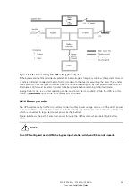
6.4.2 Normal mode – distributed bypass
In Normal mode, utility AC power is supplied to the UPSs. Each UPS then conditions the incoming AC
power and provides clean, regulated AC power to tie cabinet or distribution panel for parallel systems
of up to four modules. The applied load is shared equally among the available UPMs in the system.
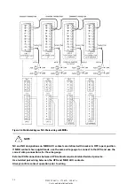
Figure 6-8 shows the path of electrical power through the parallel system when operating in Normal
mode.
Figure 6-8. Path of current through the UPSs in normal mode – distributed bypass
If the utility AC power is interrupted or is out of specification, the UPSs automatically switch to Battery
mode to support the critical load without interruption. When utility power returns, the UPSs return to
Normal mode.
If the UPSs become overloaded or unavailable, the distributed bypass system switches to Bypass
mode. The distributed bypass system automatically returns to Normal mode when the overload
condition is cleared and system operation is restored within specified limits.
Main Power Flow
Output to
Critical Load
UPS Input
Tie Cabinet
UPS 1 Output
(closed)
(closed)
(closed)
(closed)
Bypass Input
UPS 2 Output
UPS 3 Output
UPS 4 Output
De-energized
Battery
Battery
Battery
Battery
UPS 1
UPS 2
UPS 3
UPS 4
Содержание Power Xpert 9395P 250 kVA
Страница 1: ...User s and Installation Guide Power Xpert 9395P UPS 250 kVA 275 kVA 300 kVA...
Страница 2: ......
Страница 3: ...Power Xpert 9395P UPS 250 kVA 275 kVA 300 kVA User s and Installation Guide...
Страница 168: ......
Страница 169: ......
Страница 170: ...614 01919 00...


