3. Installation
3.4 Mounting
3.4.1.2 Installing the Panel-PC and Terminals
1. Insert the XP-504 into the mounting cutout from the front.
1
TOP
Fig. 16: Mounting in the installation cutout
2. As long as the device has not been secured with all holding brackets, make
sure to secure it so that it will not fall down.
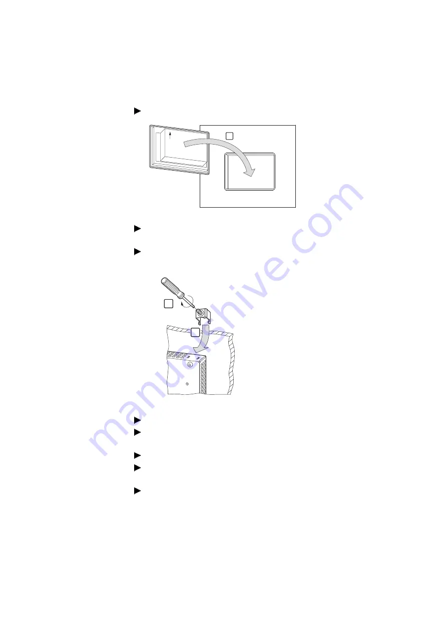
3. Insert the holding brackets into the first device cutout intended for this pur-
pose.
0.6-0.7 Nm
(5.31-6.2 lb-in)
3
4
Fig. 17: Installing the holding brackets
4. Tighten the set screw until it comes into contact with the installation surface.
5. Follow steps 3 and 4 to insert the next holding bracket at a 90° angle to the
last one you inserted.
6. Repeat steps 3 and 4 until all necessary holding brackets are installed.
7. Check that the device is in its correct, centered position and that the gasket is
in contact all around; adjust if necessary
8. Tighten the set screws in a criss-cross sequence with a max. torque of 0.6 -
0.7 Nm (5.31 -6.2 lb-in).
XP-504
04/2022 MN048028EN Eaton.com
53
Содержание 199996
Страница 1: ...Manual 04 2022 MN048028EN XP 504 Manual...
Страница 4: ......
Страница 82: ...4 Using peripheral devices External connections 4 7 DVI I 82 XP 504 04 2022 MN048028EN Eaton com...
Страница 86: ...5 Commissioning 5 2 Running the XP 504 86 XP 504 04 2022 MN048028EN Eaton com...
Страница 98: ...7 Operating System 7 2 Windows 10 Enterprise LTSC 98 XP 504 04 2022 MN048028EN Eaton com...
Страница 100: ...8 Faults 100 XP 504 04 2022 MN048028EN Eaton com...
Страница 130: ...Appendix A 2 Further usage information 130 XP 504 04 2022 MN048028EN Eaton com...


