57
After completing the inspection work in steps 1-6, replace the damaged device; after replacing the device,
use the shorting cap to short-circuit J2 of the rectifier control board CT1 and J2 of the inverter control board CT2,
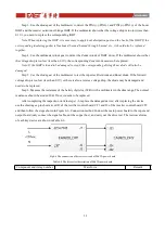
and then follow the steps shown in Figure 6-8. Connection method Connect the main power board to the input and
output board (only connect the signal cable, not the copper bus), and carry out the drive test. The test waveforms
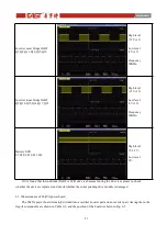
of each key device are shown in Table 6-8.
Fig.6-8 The connection of drive test circuit of 30kVA power board
Table 6-8 The driver test description of 30kVA power board
Component and its tag number
Waveform
Remark
Boost IGBT
Q1,Q2,Q3,Q4,Q5,Q6
High level
+15V±1V
;
Low level
-8V±1V
;
Frequency
40KHz
;
Inverter outer bridge IGBT
Q7,Q8,Q11,Q12,Q15,Q16
High level
+15V±1V
;
Low level
-8V±1V
;
Frequency
20KHz
;
Содержание EA990G5
Страница 4: ...7 1 Boards installation 72 7 2 Preparation before power on 72 7 3 Power on and testing 72...
Страница 9: ...5 Fig 2 5 The rear pannel of 30kVA UPS Tower Fig 2 6 The rear pannel of 10kVA 15kVA 20kVA UPS Rack...
Страница 43: ...39 Fig 5 9 The left side board of 15kVA standard model Tower Fig 5 10 The board of 15kVA model Rack...
Страница 48: ...44 Fig 5 19 The left side board of 30kVA standard model Tower...


