9
No.
Area
Function description
2
Energy flow diagram Display the energy flow state of the cabinet. Click the
corresponding work interface to view the status information.
3
Status bar
Display operation status, system time, buzzer status, alarm
status, HMI and monitoring communication status, USB status
of the cabinet.
4
Cold start
Start the UPS in battery mode. The icon will be hidden after two
minutes.
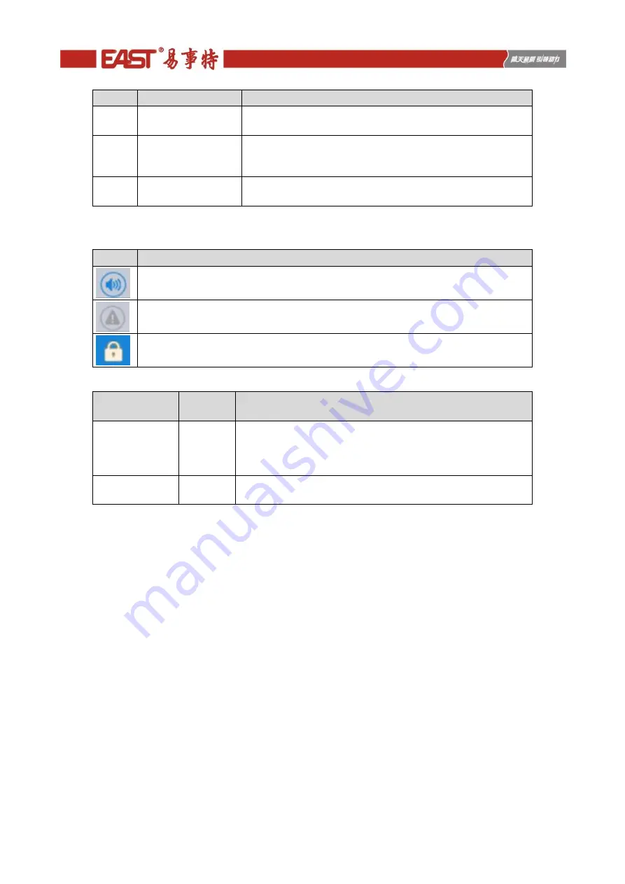
Table 2-7 Description of icons in status bar
Icon
Function description
Buzzer status, which becomes lit to indicate the buzzer enabled, and off to indicate the
buzzer disabled
Alarm status, which becomes lit to indicate an alarm, and off to indicate no alarm
Password login/logout key. After clicking, enter user password or advanced password
by the keyboard. The screen will be locked automatically.
Table 2-8 Description of password permissions
Password
permissions
Default
Function description
User password
123456
Unlock On and OFF control right and the right of common
settings and communication settings.
It can be changed in "settings - common settings - user
password".
Advanced
password
Not opened Unlock all control and setting rights.
It can be used by qualified electricians only.
2.3.3 System
In the "System" information interface, the "Mains ", "Bypass ", "Battery ", "Output", "Other", "Statistics" and
"About " information of the system can be inquired in the secondary menu at the left side.
Mains
The menu interface of the mains input is shown in Fig. 2-11, and displays information on three phases ABC
from left to right. The interface description is shown in Table 2-9.
Содержание EA990G5
Страница 4: ...7 1 Boards installation 72 7 2 Preparation before power on 72 7 3 Power on and testing 72...
Страница 9: ...5 Fig 2 5 The rear pannel of 30kVA UPS Tower Fig 2 6 The rear pannel of 10kVA 15kVA 20kVA UPS Rack...
Страница 43: ...39 Fig 5 9 The left side board of 15kVA standard model Tower Fig 5 10 The board of 15kVA model Rack...
Страница 48: ...44 Fig 5 19 The left side board of 30kVA standard model Tower...


