


48
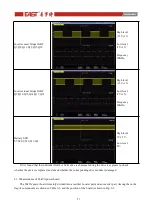
Inverter inner bridge IGBT
Q9,Q10,Q13,Q14,Q17,Q18
High level
+15V±1V
;
Low level
-8V±1V
;
Frequency
20KHz
;
Battery SCR
S7,S8,S9,S10,S11,S12
High level
1V-1.5V
;
Low level
0V
;
If it is found that the individual IGBT or SCR drive is abnormal during the drive test, please re-check
whether the device is replaced, and check whether the corresponding drive module is damaged.
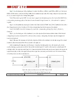
6.1.2 Maintenance of 15kVA power board
The 15kVA power board is mainly divided into a rectifier booster part and an inverter part. Among them, the
fragile components are shown in Table 6-3, and the position of the board is shown in Fig. 6-3.
Table 6-3 The fragile componments of 15kVA power board
Components
Tag Number
Specifications
Alternative
specification
Diode of input retifier
D11,D12,D13,D14,D15,D16
RHRP30120
MM30FU120K
Battery SCR
S7,S8,S9,S10,S11,S12
VS-50TPS12L-M3
CLA50E1200HB
Battery
SCR
driver
module
PCB11
Boost IGBT
Q1,Q2,Q3,Q4,Q5,Q6
IKW50N65H5
MM75G5U65BX
Inverter outer bridge
IGBT
Q7,Q8,Q11,Q12,Q15,Q16
IKW25N120T2
MM40G3U120BX
Inverter inner bridge
IGBT
Q9,Q10,Q13,Q14,Q17,Q18
IKW30N65EL5
JT050N065WED
IGBT driver module
PCB1,PCB2,PCB3,PCB4,PCB5,
PCB6,PCB7,PCB8,PCB9
Zenner diode of IGBT
driver
ZD6,ZD7,ZD8,ZD9,ZD10,ZD11,
ZD12,ZD13,ZD14,ZD15,ZD16,
ZMM18
Содержание EA990G5
Страница 4: ...7 1 Boards installation 72 7 2 Preparation before power on 72 7 3 Power on and testing 72...
Страница 9: ...5 Fig 2 5 The rear pannel of 30kVA UPS Tower Fig 2 6 The rear pannel of 10kVA 15kVA 20kVA UPS Rack...
Страница 43: ...39 Fig 5 9 The left side board of 15kVA standard model Tower Fig 5 10 The board of 15kVA model Rack...
Страница 48: ...44 Fig 5 19 The left side board of 30kVA standard model Tower...


