-10-
-11-
3.2 Rear panel description
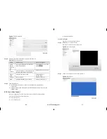
Figure 3-2 shows the rear panel of the Network Video recorders. Table 3-2 shows the
interface of rear panel.
Figure 3-2
Rear panel
Table 3-2
Real panel description
No.
Name
Description
1
Cooling fan
Start automatically when the temperature is too
high.
2
Power switch
Turn on or turn off the power.
3
Power Interface
DV12V, 5A power.
4
Audio output
3.5mm Mono audio.
5
HDMI output
HDMI video output interface.
6
VGA output
VGA DB15 video output interface.
7
RST button
Restores the factory default settings. 5 second holds.
8
Network Interface
RJ45 100Mbps network interface.
3.3 First boot
Make sure that the right of access to power NVR.
Ensure correct display HDMI or VGA interface connection.
If the front panel of the power indicator lamp does not flash please plug in the power
cable .Enable the power switch, NVR start running. If the front panel power indicator
lamp flashing Red light, please put the switch at front panel to start device.
After the device starts, the power light is solid red device starts after the self-test, and
the test results are displayed on the screen. Show in Figure 3-3. Entire boot process
takes about two minutes.
Figure 3-3
Device power on
When an exception occurs when the device self-test, this interface will stay in the lower
right of the screen, you can choose to continue or shutdown. If you choose to continue,
the device will continue to start, until the device login screen is shown.
NVR hard drive has rigorous testing, if fails, the reasons may include the following
:
Unformatted new hard disk. Go to quickly configure the hard disk is formatted
。
Formatted hard drive, the NVR supported file systems do not match
。
Hard disk is damaged
。
eLineTechnology.com


