10
Istruction Manual ISI SERIES
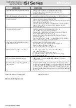
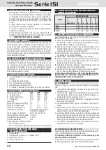
The regeneration is made up of 7 steps, all associated to the
letter “C”:
C1 backwash
C2 salt injection and rinse
C3 ri-pressurization
C4 quick rinse
C5 second backwash
C6 second quick rinse
C7 loading of water in the brine
10.3 QUICK CYCLE:
To check the correct functioning of the different regeneration
steps, follow the instructions below:
1) Press and hold down
until the display shows two lines
in vertical fall; a manual regeneration cycle will begin.
2) Wait for a few seconds, then press
. The display will
show the current step of the cycle, C1.
3) Press
at the same time to pass to the following
step of the regeneration.
4) Wait for a few seconds, then press
to see the current
step of the cycle on the display (“C2”).
Repeating the previous commands, it is possible to go past
all the 7 steps until the “service” position, and then the
display will show back the set time.
If you press and hold down
at the same time for
5 seconds, the valve, whatever its position, will go past all
the steps non-stop, until the service step
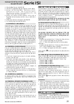
10.4 SELECTING THE REGENERATION PROGRAM
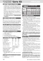
The valve is provided with 4 different regeneration programs:
U1, U2, U3, U4. Every program has different time values for
each regeneration step.
The model ISI 5 require the program “U3”
.
The models ISI 8 and ISI 12 require the program “U4”.
To select the regeneration program, press and hold down
at the same time for 5 seconds, until the display
shows the program in use.
Press
to select U4 (U3 for ISI 5) and wait for a few se-
conds until the display shows back the set time.
Press and hold down
again for 5 seconds and check
that “U4” appears on the display (U3 for ISI 5).
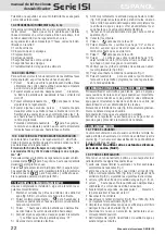
11) SETTING AT WORK
After the installation is complete, follow the procedure below:
1. Close the water inlet and outlet taps (fig. 3, B, D), then
plug in the fixture.
2. Press and hold down
at the same time for 5 se-
conds; the valve will immediatelly position to the service
step and the display will show the time.
3. Press until the display shows two horizontal lines in
vertical fall.
4. Wait for a few seconds, then press
briefly and check
that “C1” appears on the display.
5. Unplug the fixture.
6. Slowly open the water inlet by half (fig. 3, D) and leave it
in this position for about 3 minutes.
When all the air is out, open the water inlet completely.
Let the water flow abundantly until it is crystal clear;
7. In the meantime, pour some water in the brine tank and
cover the suction pipe;
8. Plug in the fixture again.
9. Press
at the same time to pass to step C2.
10. Press
briefly and check that “C2” is written on the
display; wait until the water level in the vat decreases and
almost all the water is sucked in.
11. Press
to pass to step C3.
12. Press
and check that “C3” appears on the display.
When the cycle is complete (it will take about 10 minu-
tes), check that the vat still contains some water.
13. Check that the inlet and outlet taps are completely open
(fig. 3, B, D).
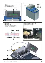
14. Add salt, up to more than half of the vat (fig. 7).
15. Press
briefly, and the display will show a flashing
dot. It’s now possible to program a regeneration at a fixed
time.
12) ADJUSTING THE MIXER SCREW
The water softener supplies water free of hardness. In some
cases, however, a hardness residual in the water can be im-
portant.
The mixer allows a certain amount of water to pass directly
from the inlet to the outlet of the water softener, without being
softened by resins.
Screwing up the mixer screw (fig. 8, E) you can gradually
increase the hardness of the outcoming water.
Please remember that this operation must be carried out very
carefully.
At the end of the adjustment, we advise you to let some water
flow out and to measure its hardness.
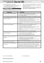
13) MAINTENANCE
13.1 FOR THE USER
Maintenance for users only consists in refilling the brine pe-
riodically with sodium chloride (NaCl, common salt), in lack
of which the water softener will not be able to eliminate water
limy hardness.
ATTENTION! Never use substances different from
common salt (NaCl).
13.2 FOR INSTALLERS
For an ideal working, it is advisable to perform the following
operations periodically:
1) Clean the brine and remove any sediment from the suction
pipe (fig. 1) every six months;
2. Clean the injector (fig. 8, B) and its filter (fig. 8, A) at least
once a year, following the instructions reported below:
• Close the water inlet and outlet taps (fig. 3, B, D)
• Press and hold down
until the display shows two hori-
zontal lines in vertical fall.
• Wait for a few seconds, then press
briefly to visualize
the cycle step (C1).
• Unplug the fixture.
• Unscrew and remove the ejector (fig. 8, B), the filter (fig. 8,
A) and the brine control (fig. 8, C).
• Wash the components with water and make sure the hole
in the ejector isn’t blocked.
• Carefully place the parts again in their seats.
• Slowly open the water inlet and outlet taps, and wait for a
few minutes.
• Plug the fixture.
• Press and hold down
at the same time for 5 se-
conds. The valve will automatically position to service step.
• The display will then show back the time (fig. 6, B)
14) USEFUL INFORMATION
Experience teaches that often malfunctioning of water softe-
ners is caused by an incorrect outlet pipe installation (fig. 4,
A). For this reason, we advise you to perform a correct instal-
lation (fig. 3, F), using the outlet pipe provided.
Where possible, it is advisable to install a filter before the
water softener to get rid of substances that could compromise
the good functioning of the fixture.
ENGLISH
instruction manual
water softener
ISI Series


