24
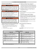
6.5 Approved Venting Materials
6 - COMBUSTION AIR AND VENT PIPING
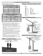
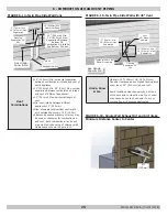
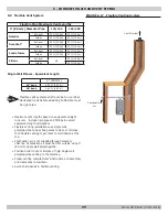
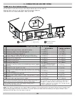
6.6 Vent Termination
•
Terminate combustion air and vent pipes with fittings or
coaxial vent kit.
Use horizontal pipe for vent and 90° elbow for
combustion air termination when using fittings.
• Separate vent terminal from air inlet terminal to prevent
flue gas recirculation. If T-Terminal is used on flue pipe
at sidewall, air inlet terminal shall be at least 36" or more
away from vent terminal.
• Locate combustion air termination as far as possible from
swimming pool, swimming pool pump house, and other
sources of airborne chlorine.
• Locate combustion air and vent terminals as required by
authority having jurisdiction.
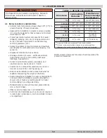
Vent Material Options
125 & 150
165 & 205
1
4" / 2" [100 mm / 50 mm] polypropylene coaxial.
1
5"/3" [125mm/80m] polypropylene coaxial.
2
3" [80mm] polypropylene twin pipe.
Shall be polypropylene on BOTH intake and
exhaust.
2
3" [80mm] polypropylene twin pipe.
Shall be polypropylene on BOTH intake and
exhaust.
3
3" [80mm] flexible polypropylene for chimney
exhaust vent, shall have rigid 3" [80mm]
polypropylene on air intake.
3
2" [50mm] polypropylene twin pipe.
Shall be polypropylene on BOTH intake and
exhaust.
4
3" [80mm] Twin pipe CPVC.
PVC optional on intake ONLY.
4
3" [80mm] flexible polypropylene for chimney
exhaust vent, shall have rigid 3" [80mm]
polypropylene on air intake.
5
3" [80mm] Twin pipe CPVC.
PVC optional on intake ONLY.
* Note: Adapters and fittings used with all vent systems shall be from same manufacturer and compatible with the vent
pipe. See list for approved Manufacturers.
Installation shall conform to requirements of authority having
jurisdiction or in absence of such requirements:
• USA - National Fuel Gas Code, ANSI Z223.1/NFPA 54.
• Canada - Natural Gas and Propane Installation Code,
CAN/CSA B149.1
1.
Venting shall be properly supported.
WARNING
Manufacturer recommends this condensing boiler be
vented with approved polypropylene venting material.
Use only materials listed below for vent pipe, intake
air pipe, and fittings. Failure to comply could result in
death or serious injury.
!
WARNING
Do not use cellular core pipe. Only specified sized
pipes are to be used. When using venting material
other than boiler manufacturer's venting, note the
correct installation procedure. Failure to follow these
instructions could result in death, or serious injury.
!
WARNING
•
Covering non-metallic vent pipe and fittings with
thermal insulation shall be prohibited.
•
Use of cellular core PVC for venting flue gas could
result in death, or serious injury.
• Coaxial venting shall be fastened with screws. Dual
flue venting is NOT fastened with screws.
!
2.
Boiler shall not support any type of vent system.
3.
All piping, glue, solvents, cleaners, fittings and
components must conform to ASTM and ANSI standards.
In Canada ULC S636 and in the USA UL 1738 schedule 40
CPVC are the only approved vent system to be used as an
alternative to polypropylene venting for the exhaust pipe
4.
Manufacturer requires use of a spring clamp at every
push-fit gasket connection when using a single wall
polypropylene vent system.
Approved Polypropylene Manufacturers
* Natalini
* DuraVent
®
*Centrotherm
* Z-Flex
®
Note: Maximum equivalent length may vary between
manufacturers.
240011947 REV B, [03/31/2018]
Содержание DCB-125
Страница 2: ...DCC 205 ...
Страница 4: ...DCB 165 ...
Страница 65: ...61 APPENDIX A WIRING DIAGRAMS A 1 MODELS 125 Heat Only 240011947 REV B 03 31 2018 ...
Страница 66: ...62 APPENDIX A WIRING DIAGRAMS A 2 MODELS 165 Heat Only 240011947 REV B 03 31 2018 ...
Страница 67: ...63 APPENDIX A WIRING DIAGRAMS A 3 MODELS 150 Combi 240011947 REV B 03 31 2018 ...
Страница 68: ...64 APPENDIX A WIRING DIAGRAMS A 4 MODELS 205 Combi 240011947 REV B 03 31 2018 ...
Страница 69: ...65 NOTES 240011947 REV B 03 31 2018 ...
Страница 70: ...66 NOTES 240011947 REV B 03 31 2018 ...
Страница 81: ...9 125 WITH ZONE CIRCULATOR PUMPS 125 with Zone Circulator Pumps PN 240011430 REV G 03 31 18 ...
Страница 84: ...12 125 WITH ZONE VALVES PIPING DIAGRAM 125 with Zone Valves PN 240011430 REV G 03 31 18 ...
Страница 87: ...15 165 WITH ZONE CIRCULATOR PUMPS PIPING DIAGRAM 165 with Zone Circulator Pumps PN 240011430 REV G 03 31 18 ...
Страница 90: ...18 165 with Zone Valves 165 WITH ZONE VALVES PIPING DIAGRAM PN 240011430 REV G 03 31 18 ...
Страница 94: ...22 150 205 WITH ZONE PUMPS WIRING DIAGRAM 150 205 With Zone Pumps PN 240011430 REV G 03 31 18 ...
Страница 95: ...23 150 205 with Zone Valves 150 205 WITH ZONE VALVES PIPING DIAGRAM PN 240011430 REV G 03 31 18 ...
Страница 96: ...24 150 205 WITH ZONE VALVES WIRING DIAGRAM 150 205 With Zone Valves PN 240011430 REV G 03 31 18 ...
Страница 102: ...30 MODEL 125 Heat Only 125 HEAT ONLY WIRING DIAGRAM PN 240011430 REV G 03 31 18 ...
Страница 103: ...31 MODEL 165 Heat Only 165 HEAT ONLY WIRING DIAGRAM PN 240011430 REV G 03 31 18 ...
Страница 104: ...32 MODEL 150 Combi 150 COMBI WIRING DIAGRAM PN 240011430 REV G 03 31 18 ...
Страница 105: ...33 MODEL 205 Combi 205 COMBI WIRING DIAGRAM PN 240011430 REV G 03 31 18 ...
Страница 110: ...38 Low Water Cutoff Detail LOW WATER CUTOFF NO NO YES PN 240011430 REV G 03 31 18 ...
Страница 111: ...39 NOTES PN 240011430 REV G 03 31 18 ...
Страница 112: ......
Страница 115: ......
Страница 116: ......

