60
• METRIC GAS METERS
Natural Gas
MBH
=
127,116 x cu meters
Seconds
For example: Gas Meter measures 0.1 cubic Meters in 100
seconds
MBH
=
127,116 x 0.1
= 127 MBH
100
Propane Gas (LP)
MBH
=
383,482 x cu meters
Seconds
• NATIONAL BOARD OF BOILER AND PRESSURE VESSEL
INSPECTORS -
Group composed of boiler and pressure
vessel inspectors representing states, cities and provinces
enforcing pressure equipment laws and regulations.
• PRESSURE TEST
- Operation performed to verify gas
tight integrity of gas piping following its installation or
modification.
• PURGE
- To free gas conduit of air or gas, or mixture of gas
and air.
• PURGE TIME
- Period of time intended to allow for
dissipation of any unburned gas or residual products of
combustion.
• QUALIFIED AGENCY
- Any individual, firm, corporation, or
company engaged in and responsible for:
• Installation, testing, or replacement of gas piping, or
connection, installation, testing, repair or servicing
of appliances and equipment.
• Experienced in such work.
• Familiar with all precautions required.
• Complies with all requirements of authority having
jurisdiction.
• SAFETY RELIEF VALVE
- Valve designed to relieve
pressure in hot water supply system when pressure exceeds
pressure capability of equipment.
• SAFETY SHUTOFF DEVICE
- Device that will shut off gas
supply to controlled burner in event source of ignition fails.
• SEDIMENT TRAP
- Gas piping arrangement designed to
collect any liquid or solid contaminant before reaching gas
valve.
• SERVICE
-Supply, installation, or maintenance of goods
carried out by a Qualified Installer / Service Technician.
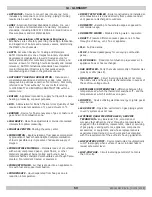
14 - GLOSSARY
• TWO PIPE SYSTEM
- Type of venting that allows for
exhaust flue and intake air piping to be separated from each
other. Fresh air may be drawn in at a different area from
where flue terminal is located.
• VENT
- Passageway used to convey flue gases from
appliance vent connector to outdoors.
• VENTING SYSTEM
- Continuous open passageway from
of appliance vent connector to outdoors for purpose of
removing flue or vent gases.
240011947 REV B, [03/31/2018]
Содержание DCB-125
Страница 2: ...DCC 205 ...
Страница 4: ...DCB 165 ...
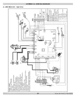
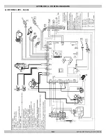
Страница 65: ...61 APPENDIX A WIRING DIAGRAMS A 1 MODELS 125 Heat Only 240011947 REV B 03 31 2018 ...
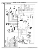
Страница 66: ...62 APPENDIX A WIRING DIAGRAMS A 2 MODELS 165 Heat Only 240011947 REV B 03 31 2018 ...
Страница 67: ...63 APPENDIX A WIRING DIAGRAMS A 3 MODELS 150 Combi 240011947 REV B 03 31 2018 ...
Страница 68: ...64 APPENDIX A WIRING DIAGRAMS A 4 MODELS 205 Combi 240011947 REV B 03 31 2018 ...
Страница 69: ...65 NOTES 240011947 REV B 03 31 2018 ...
Страница 70: ...66 NOTES 240011947 REV B 03 31 2018 ...
Страница 81: ...9 125 WITH ZONE CIRCULATOR PUMPS 125 with Zone Circulator Pumps PN 240011430 REV G 03 31 18 ...
Страница 84: ...12 125 WITH ZONE VALVES PIPING DIAGRAM 125 with Zone Valves PN 240011430 REV G 03 31 18 ...
Страница 87: ...15 165 WITH ZONE CIRCULATOR PUMPS PIPING DIAGRAM 165 with Zone Circulator Pumps PN 240011430 REV G 03 31 18 ...
Страница 90: ...18 165 with Zone Valves 165 WITH ZONE VALVES PIPING DIAGRAM PN 240011430 REV G 03 31 18 ...
Страница 94: ...22 150 205 WITH ZONE PUMPS WIRING DIAGRAM 150 205 With Zone Pumps PN 240011430 REV G 03 31 18 ...
Страница 95: ...23 150 205 with Zone Valves 150 205 WITH ZONE VALVES PIPING DIAGRAM PN 240011430 REV G 03 31 18 ...
Страница 96: ...24 150 205 WITH ZONE VALVES WIRING DIAGRAM 150 205 With Zone Valves PN 240011430 REV G 03 31 18 ...
Страница 102: ...30 MODEL 125 Heat Only 125 HEAT ONLY WIRING DIAGRAM PN 240011430 REV G 03 31 18 ...
Страница 103: ...31 MODEL 165 Heat Only 165 HEAT ONLY WIRING DIAGRAM PN 240011430 REV G 03 31 18 ...
Страница 104: ...32 MODEL 150 Combi 150 COMBI WIRING DIAGRAM PN 240011430 REV G 03 31 18 ...
Страница 105: ...33 MODEL 205 Combi 205 COMBI WIRING DIAGRAM PN 240011430 REV G 03 31 18 ...
Страница 110: ...38 Low Water Cutoff Detail LOW WATER CUTOFF NO NO YES PN 240011430 REV G 03 31 18 ...
Страница 111: ...39 NOTES PN 240011430 REV G 03 31 18 ...
Страница 112: ......
Страница 115: ......
Страница 116: ......

