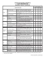
Inspection Items
Date Completed
Year
1
Year
2
Year
3
Year
*4
Piping
Near boiler piping
Check boiler and system piping for any sign of
leakage, verify pipes are properly supported.
Vent
Check condition of all vent pipes and joints. Verify
vent piping terminations are free of obstructions
and blockages.
Safety Relief Valve
Follow manufacturers instructions for maintenance
and repair.
System
Visual
Do full visual inspection of ALL system
components.
Functional
Test all functions of the system (heat and safety)
Temperatures
Verify safe settings on boiler or anti-scald valve.
Verify programmed temperature settings.
Electrical
Connections
Check wire connection. Verify connections are
tight.
Smoke and Co detector
Verify devices are installed and working properly.
Change batteries if necessary.
Circuit Breakers
Check that circuit breaker is clearly labeled and
operates correctly.
Chamber/
Burner
Combustion Chamber
Check burner and combustion chamber. Clean
following directions in maintenance section of IOM.
Replace gaskets whenever checking combustion
chamber.
Spark Electrode
Clean. Set gap according to IOM directions. Clean
probe with plumbers cloth to remove oxides.
Flame Sensor
Clean probe.
Condensate
Neutralizer
Check condensate neutralizer - replace if
necessary.
Condensate pipe/trap
Disconnect condensate pipe. Clean out any dirt
or accumulation. Fill with water level of outlet
and reinstall. NOTE: verify flow of condensate,
make sure hose is properly connected during final
inspection.
Gas
Pressure
Measure incoming pas pressure (3.5 to 14" WC).
Pressure drop
Measure drop in pressure on light off (no more
than 1" WC).
Leaks
Check gas piping. Test for leaks and signs of aging.
Make sure all pipes are properly supported.
Combustion CO/CO
₂
Levels
Check CO and CO
₂
level in exhaust. See Start-up
Procedures for ranges. Record at high and low fire.
Safety
All Sensors
Check continuity of all sensors. Replace if corroded.
Verify all connections through ohms reading.
Final
Inspection
Check List
Verify you have completed entire check list.
Homeowner
Review findings and service with Homeowner.
Required
Inspection Schedule
To Be Completed By
Qualified Service Technician
* Continue inspections beyond 4th year. Maintenance should continue annually for the life of the boiler to ensure
safe worry free operation.
PN 240011561 REV A, [06/29/2016]
Содержание DCB-125
Страница 2: ...DCC 205 ...
Страница 4: ...DCB 165 ...
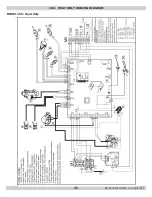
Страница 65: ...61 APPENDIX A WIRING DIAGRAMS A 1 MODELS 125 Heat Only 240011947 REV B 03 31 2018 ...
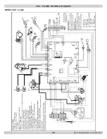
Страница 66: ...62 APPENDIX A WIRING DIAGRAMS A 2 MODELS 165 Heat Only 240011947 REV B 03 31 2018 ...
Страница 67: ...63 APPENDIX A WIRING DIAGRAMS A 3 MODELS 150 Combi 240011947 REV B 03 31 2018 ...
Страница 68: ...64 APPENDIX A WIRING DIAGRAMS A 4 MODELS 205 Combi 240011947 REV B 03 31 2018 ...
Страница 69: ...65 NOTES 240011947 REV B 03 31 2018 ...
Страница 70: ...66 NOTES 240011947 REV B 03 31 2018 ...
Страница 81: ...9 125 WITH ZONE CIRCULATOR PUMPS 125 with Zone Circulator Pumps PN 240011430 REV G 03 31 18 ...
Страница 84: ...12 125 WITH ZONE VALVES PIPING DIAGRAM 125 with Zone Valves PN 240011430 REV G 03 31 18 ...
Страница 87: ...15 165 WITH ZONE CIRCULATOR PUMPS PIPING DIAGRAM 165 with Zone Circulator Pumps PN 240011430 REV G 03 31 18 ...
Страница 90: ...18 165 with Zone Valves 165 WITH ZONE VALVES PIPING DIAGRAM PN 240011430 REV G 03 31 18 ...
Страница 94: ...22 150 205 WITH ZONE PUMPS WIRING DIAGRAM 150 205 With Zone Pumps PN 240011430 REV G 03 31 18 ...
Страница 95: ...23 150 205 with Zone Valves 150 205 WITH ZONE VALVES PIPING DIAGRAM PN 240011430 REV G 03 31 18 ...
Страница 96: ...24 150 205 WITH ZONE VALVES WIRING DIAGRAM 150 205 With Zone Valves PN 240011430 REV G 03 31 18 ...
Страница 102: ...30 MODEL 125 Heat Only 125 HEAT ONLY WIRING DIAGRAM PN 240011430 REV G 03 31 18 ...
Страница 103: ...31 MODEL 165 Heat Only 165 HEAT ONLY WIRING DIAGRAM PN 240011430 REV G 03 31 18 ...
Страница 104: ...32 MODEL 150 Combi 150 COMBI WIRING DIAGRAM PN 240011430 REV G 03 31 18 ...
Страница 105: ...33 MODEL 205 Combi 205 COMBI WIRING DIAGRAM PN 240011430 REV G 03 31 18 ...
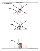
Страница 110: ...38 Low Water Cutoff Detail LOW WATER CUTOFF NO NO YES PN 240011430 REV G 03 31 18 ...
Страница 111: ...39 NOTES PN 240011430 REV G 03 31 18 ...
Страница 112: ......
Страница 115: ......
Страница 116: ......

