6
GENERAL INFORMATION - HYDRONIC PIPING
General Information:
Piping installation, materials, and joining methods shall
conform to requirements of authority having jurisdiction or
in absence of such requirements:
• USA
- National Fuel Gas Code, ANSI Z223.1/NFPA 54
• Canada
- Natural Gas and Propane Installation Code,
CAN/CSA B149.1
Manufacturer Requirements/Recommendations:
•
Manufacturer requires all domestic hot water (DHW)
installations use an anti-scald valve. Local codes
may require additional equipment (expansion tank,
relief valves, etc.) Select and size equipment to suit
installation and meet code requirements.
• Use of a water filter on incoming water supply line.
• If the piping manifold is not used the ASME
temperature and pressure relief valve and
temperature and pressure gauge shall be installed
to conform to requirements of the authority having
jurisdiction. Refer to appropriate manufacturer
instructions for installation requirements.
• If the piping manifold is not used, a primary /
secondary piping arrangement is manufacturer
recommended. A maximum of 12” of separation
between the supply and return pipe (closely spaced
tees) of the boiler shall be maintained.
• Limit combined supply and return pipe lengths to
maximum linear lengths of 20 ft (6.1 m) between
boiler and closely spaced tees, when minimum
¾” NPT pipe size is used. Linear length may be
increased if supply and return pipe size is increased
to limit pressure drop.
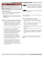
Note
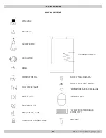
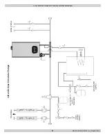
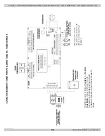
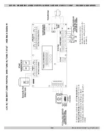
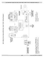
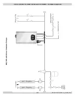
Provided Wiring and Piping illustrations
are meant to show system concepts only.
Installer is responsible for all equipment
required by authority having jurisdiction.
Note
Arrange piping to prevent water dripping
onto boiler.
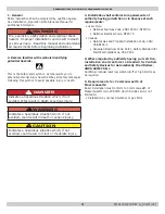
WARNING
Burn and scald hazard! Manufacturer requires
installation of field supplied anti-scald valve.
Failure to follow these instructions could result in
death or serious injury.
!
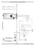
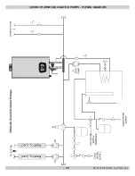
All piping diagrams are shown with optional DHW Indirect
Tank where applicable.
Use of Indirect Storage Tank (DHW):
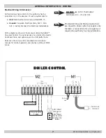
☐
Use either DHW sensor or Indirect Tank Thermostat
to interface with boiler. Wire to M2 terminals #9 and
#10.
☐
Use of booster pump to increase flow rate to indirect
tank is not recommended by manufacturer.
☐
Locate tank as close to boiler as possible.
☐
Size DHW tank, piping, and system to use only internal
boiler pump.
☐
See available pump/flow rate chart, page 35 of this
manual.
☐
Change P03 on boiler for application as specified on the
wire diagram and Boiler Control section of Installation,
Operation & Maintenance Manual supplied with the
boiler.
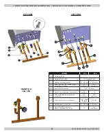
The Labor Saver Piping Manifold, which is supplied with
each boiler, is shown with most of the following piping
diagrams.
PN 240011430 REV G, [03/31/18]
Содержание DCB-125
Страница 2: ...DCC 205 ...
Страница 4: ...DCB 165 ...
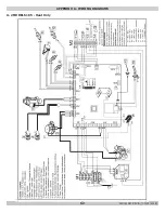
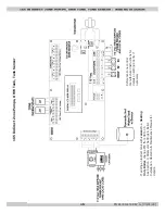
Страница 65: ...61 APPENDIX A WIRING DIAGRAMS A 1 MODELS 125 Heat Only 240011947 REV B 03 31 2018 ...
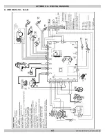
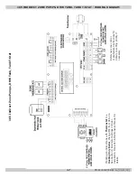
Страница 66: ...62 APPENDIX A WIRING DIAGRAMS A 2 MODELS 165 Heat Only 240011947 REV B 03 31 2018 ...
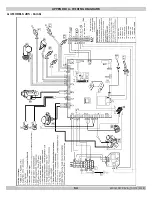
Страница 67: ...63 APPENDIX A WIRING DIAGRAMS A 3 MODELS 150 Combi 240011947 REV B 03 31 2018 ...
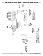
Страница 68: ...64 APPENDIX A WIRING DIAGRAMS A 4 MODELS 205 Combi 240011947 REV B 03 31 2018 ...
Страница 69: ...65 NOTES 240011947 REV B 03 31 2018 ...
Страница 70: ...66 NOTES 240011947 REV B 03 31 2018 ...
Страница 81: ...9 125 WITH ZONE CIRCULATOR PUMPS 125 with Zone Circulator Pumps PN 240011430 REV G 03 31 18 ...
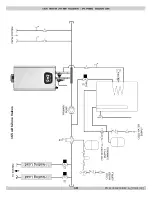
Страница 84: ...12 125 WITH ZONE VALVES PIPING DIAGRAM 125 with Zone Valves PN 240011430 REV G 03 31 18 ...
Страница 87: ...15 165 WITH ZONE CIRCULATOR PUMPS PIPING DIAGRAM 165 with Zone Circulator Pumps PN 240011430 REV G 03 31 18 ...
Страница 90: ...18 165 with Zone Valves 165 WITH ZONE VALVES PIPING DIAGRAM PN 240011430 REV G 03 31 18 ...
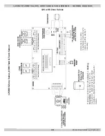
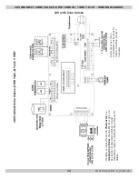
Страница 94: ...22 150 205 WITH ZONE PUMPS WIRING DIAGRAM 150 205 With Zone Pumps PN 240011430 REV G 03 31 18 ...
Страница 95: ...23 150 205 with Zone Valves 150 205 WITH ZONE VALVES PIPING DIAGRAM PN 240011430 REV G 03 31 18 ...
Страница 96: ...24 150 205 WITH ZONE VALVES WIRING DIAGRAM 150 205 With Zone Valves PN 240011430 REV G 03 31 18 ...
Страница 102: ...30 MODEL 125 Heat Only 125 HEAT ONLY WIRING DIAGRAM PN 240011430 REV G 03 31 18 ...
Страница 103: ...31 MODEL 165 Heat Only 165 HEAT ONLY WIRING DIAGRAM PN 240011430 REV G 03 31 18 ...
Страница 104: ...32 MODEL 150 Combi 150 COMBI WIRING DIAGRAM PN 240011430 REV G 03 31 18 ...
Страница 105: ...33 MODEL 205 Combi 205 COMBI WIRING DIAGRAM PN 240011430 REV G 03 31 18 ...
Страница 110: ...38 Low Water Cutoff Detail LOW WATER CUTOFF NO NO YES PN 240011430 REV G 03 31 18 ...
Страница 111: ...39 NOTES PN 240011430 REV G 03 31 18 ...
Страница 112: ......
Страница 115: ......
Страница 116: ......


