7
GENERAL INFORMATION - WIRING
Electical Wiring Information:
All field wiring shall conform to the authority having
jurisdiction or, in the absence of such requirements to:
• USA
: National Electrical Code, ANSI/NFPA 70,
• Canada
: Canadian Electrical Code, Part I, CSA
C22.1: Safety Standard for Electrical Installations.
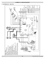
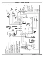
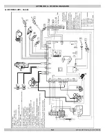
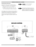
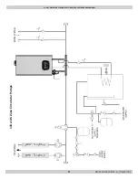
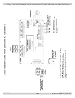
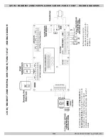
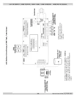
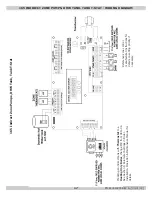
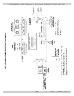
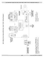
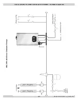
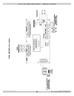
Wiring diagrams shown in this manual utilize the ARGO™
Universal Control, the optional use of an Indirect Domestic
Hot Water Tank, and optional use of a H2O Buffer Tank.
Reference the zone control manufacturer instruction
manual for control operation and priority sertting of DHW
zones.
Note
DO NOT
use 120 V thermostat
terminals (m1- #1 and #2).
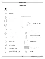
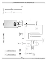
Provided Wiring and Piping illustrations
are meant to show system concepts only.
Installer is responsible for all equipment
required by authority having jurisdiction.
Note
SUPPLY Cord
120V/60HZ
BOILER CONTROL
DHW Indirect
Tank Sensor
or
DHW Indirect
Tank Aquastat
(Heating Only
Boilers
Do Not
Use
Outdoor Reset
Zone Control
T-Stat
PN 240011430 REV G, [03/31/18]
Содержание DCB-125
Страница 2: ...DCC 205 ...
Страница 4: ...DCB 165 ...
Страница 65: ...61 APPENDIX A WIRING DIAGRAMS A 1 MODELS 125 Heat Only 240011947 REV B 03 31 2018 ...
Страница 66: ...62 APPENDIX A WIRING DIAGRAMS A 2 MODELS 165 Heat Only 240011947 REV B 03 31 2018 ...
Страница 67: ...63 APPENDIX A WIRING DIAGRAMS A 3 MODELS 150 Combi 240011947 REV B 03 31 2018 ...
Страница 68: ...64 APPENDIX A WIRING DIAGRAMS A 4 MODELS 205 Combi 240011947 REV B 03 31 2018 ...
Страница 69: ...65 NOTES 240011947 REV B 03 31 2018 ...
Страница 70: ...66 NOTES 240011947 REV B 03 31 2018 ...
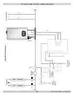
Страница 81: ...9 125 WITH ZONE CIRCULATOR PUMPS 125 with Zone Circulator Pumps PN 240011430 REV G 03 31 18 ...
Страница 84: ...12 125 WITH ZONE VALVES PIPING DIAGRAM 125 with Zone Valves PN 240011430 REV G 03 31 18 ...
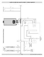
Страница 87: ...15 165 WITH ZONE CIRCULATOR PUMPS PIPING DIAGRAM 165 with Zone Circulator Pumps PN 240011430 REV G 03 31 18 ...
Страница 90: ...18 165 with Zone Valves 165 WITH ZONE VALVES PIPING DIAGRAM PN 240011430 REV G 03 31 18 ...
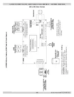
Страница 94: ...22 150 205 WITH ZONE PUMPS WIRING DIAGRAM 150 205 With Zone Pumps PN 240011430 REV G 03 31 18 ...
Страница 95: ...23 150 205 with Zone Valves 150 205 WITH ZONE VALVES PIPING DIAGRAM PN 240011430 REV G 03 31 18 ...
Страница 96: ...24 150 205 WITH ZONE VALVES WIRING DIAGRAM 150 205 With Zone Valves PN 240011430 REV G 03 31 18 ...
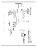
Страница 102: ...30 MODEL 125 Heat Only 125 HEAT ONLY WIRING DIAGRAM PN 240011430 REV G 03 31 18 ...
Страница 103: ...31 MODEL 165 Heat Only 165 HEAT ONLY WIRING DIAGRAM PN 240011430 REV G 03 31 18 ...
Страница 104: ...32 MODEL 150 Combi 150 COMBI WIRING DIAGRAM PN 240011430 REV G 03 31 18 ...
Страница 105: ...33 MODEL 205 Combi 205 COMBI WIRING DIAGRAM PN 240011430 REV G 03 31 18 ...
Страница 110: ...38 Low Water Cutoff Detail LOW WATER CUTOFF NO NO YES PN 240011430 REV G 03 31 18 ...
Страница 111: ...39 NOTES PN 240011430 REV G 03 31 18 ...
Страница 112: ......
Страница 115: ......
Страница 116: ......


