background image

DRAFT

Installation / Putting into operation 

Cafitesse 100 Next Generation

August 2009  

2 - 19

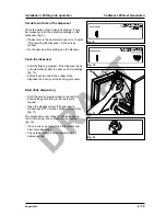
Set date and time of the dispenser 

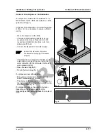
When the water in the boiler is heated up, it may 

be necessary to do the date/time settings on the 

dispenser (fig. 9).

Please refer to the operator manual or to chapter 

‚Programming the dispenser‘ of the service 

manual.
Do the date and time settings on the disenser.

Flush the dispenser

Start the flushing program, if the dispenser does 

not automatically after the date and time settings 

(fig. 10).
Put the flush bin under the outlets of the 

dispenser and carry out the flushing procedure.

Start drink dispensing

Start the service programming mode and do 

drink settings according to the customer‘s 

request.
Open the dispenser door (

10

) and insert a 

product pack (

11

) into the cooling compartment 

(fig. 11)

The dispenser is now ready for drink dispensing, 

the ‚Aroma-Lady‘ icon is shown on the display 


(fig. 12).

Place a cup or pot under the drink outlets and 

start some deliveries.

Check taste, aroma and temperature of the 

delivered drink. 

Fig. 

Fig. 10

Fig. 11

Fig. 12

10

11

Содержание Cafitesse 110

Страница 1: ...DRAFT Version August 2009 D R A F T Service Manual Cafitesse 110 Cafitesse 120 Next Generation ...

Страница 2: ... 2009 Douwe Egberts Coffee Systems International DRAFT Version August 2009 D R A F T ...

Страница 3: ...ion putting into operation 2 Transport handling of the dispenser during transport 2 1 Space and connection requirements 2 2 Technical specification 2 3 Checklist instructions for the customer 2 4 Transfer of the dispenser to the customer 2 5 External options 2 6 Unpacking 2 7 Installation of the dispenser 2 8 ...

Страница 4: ...on on the packaging of the dispenser will be added Storage and transport in general ATTENTION Transport the dispenser carefully Do not throw the dispenser or handle it incorrectly Do not transport several dispensers on top of each other unless they are fixed to a pallet as shown in the following section Only transport the dispenser in an upright position When storing the dispenser ensure that it i...

Страница 5: ...drain the residual water Pack the dispenser in such a manner that a safe transport is guaranteed Use the original packageing if possible fig 1 2 The dispenser must have been cleaned correctly before you store it for a longer period of time When used dispensers are stored for a long time the inlet valve of the water supply hose towards the boiler as well as the cold water inlet valve option cold wa...

Страница 6: ...e legal regulations Customer Water supply line dynamic pressure of min 0 8 bar at 10 liters minute min 11 6 psi at 2 6 USgal minute static pressure of max 10 bar 145 psi temperature of max 60 C 140 F Use a stop valve and a non return valve Hot water connection For the connection of the dispenser to a hot water supply higher than 60 C 140 F a hot water inlet valve must be installed in the dispenser...

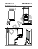
Страница 7: ...Generation August 2009 2 Space requirements Cafitesse 110NG water supply hose power cord 260 mm 10 2 in 453 mm 17 8 in 521 mm 20 5 in 2 6 0 m m 1 0 2 in 260 mm 10 2 in 770 mm 30 3 in 117 mm 4 6 in 210 mm 8 3 in 260 mm 10 2 in 13 mm 0 5 in 783 mm 30 8 in 50 mm 2 0 in ...

Страница 8: ... operation 2 August 2009 Space requirements Cafitesse 120NG water supply hose power cord 260 mm 10 2 in 453 mm 17 8 in 521 mm 20 5 in 2 6 0 m m 1 0 2 in 50 mm 2 0 in 260 mm 10 2 in 850 mm 33 5 in 117 mm 4 6 in 210 mm 8 3 in 260 mm 10 2 in 13 mm 0 5 in 863 mm 34 0 in ...

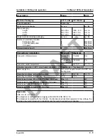
Страница 9: ...nt Boiler capacity 1 phase 3 phase Maximum consumed power x x x x kW Boiler contents 9 2 4 Ltr USgal Heating Elements at 230V x x x x x x x x kW Heating Elements at 240V USA x x x x x x kW Heating Elements at 208V USA x x x x x x kW Heating Elements at 120V USA x x kW Boiler temperature 96 205 C F Boiler temperature energy saving mode 63 145 C F Hourly capacity coffee at max heating power xx xx Lt...

Страница 10: ...mal when option chocolate delivery is installed Dispensing point s measurements Clearance between drink outlet and cup tray 117 4 6 mm in Clearance between drink outlet and cup tray 210 8 3 mm in Max clearance with drip tray removed 260 10 2 mm in Clearance between drink outlet and drip tray with air pot extension kit xxx mm in Max clearance with drip tray removed xxx mm in Max pot diameter xxx mm...

Страница 11: ... dynamic at 2 6 USgal min 140 static Psi Connection water temperature 0 60 140 C F Hot water connection 60 C or pre heater connection Requires use of pre heater kit Water supply line 1 2 or 3 8 supply line with 3 4 BSP con necting piece Operating conditions ambient temperature 5 41 32 90 C F Operating conditions ambient humidity 10 70 Rated power Europe 230 240 VAC 1 phase 16 A fuse Max 3 5 kW Rat...

Страница 12: ...D R A F T Cafitesse 100 Next Generation Installation Putting into operation 2 10 August 2009 2 4 Checklist instructions for the customer ...

Страница 13: ...D R A F T Installation Putting into operation Cafitesse 100 Next Generation August 2009 2 11 2 5 Transfer if the dispenser to the customer incl HACCP Hazard And Critical Control Points ...

Страница 14: ...D R A F T Cafitesse 100 Next Generation Installation Putting into operation 2 12 August 2009 2 6 External options to be used by MSUs and distributors for national information e g on external filters ...

Страница 15: ...ion blind buttons for respective dispenser types Operator USB key except for USA Operator manual electronic version on operator USB key printed version for USA Sticker sheet including drink name stickers and preselection stickers in the language of the country For Cafitesse 120 NG dispensers only Mixing bowl exchange kit For USA only Connection pieces for US mains water supply Water filter kit 2 7...

Страница 16: ...ls for the installation Tools required for Service USB key or Windows based service device with USB connector the programming of customer specific settings Several screw drivers the installation of customer specific kits Pressure gauge the measuring of the water pressure Adapter cables Use adapter cables for the connection to European mains sockets that are different from the German French safety ...

Страница 17: ...g C120NG WITTENBORG S2LP1 MKT 050911 123456 VOLT TOTAL HEIZUNG HEATING CHAUFFAGE V kW kW A bar Bar W A L HZ CPS KÜHLUNG REFRIGERATION REFROIDISSMENT KESSELINHALT BOILER CAP CAPACITE DE BUILLOIRE COMPRESSOR COMPRESSEUR 230 240 3 5 3 3 16 ATM 50 60 9 IPX1 Min dyn line pres 0 8bar Max st line pres 10 bar N W Global Vending L L E T S E G N I E R E W E T TE T C L E S S E U L A V 3 E S E E N N O I T C L...

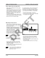
Страница 18: ...n the tap If the outlet needs to be extended use a hose with an interior diameter of at least 15 mm 0 59 in Read the dynamic pressure on the pressure gauge The pressure should always be higher than 0 8 bar 11 5 psi Close the tap and read the static line pressure in the pressure gauge The value should be less than 10 bar 145 psi Power supply and power supply cable Observe the specifications on the ...

Страница 19: ...with the kit Connect the dispenser to the water supply Ensure that the water stop valve connected to the supply line seales properly If the dispenser is equipped for the delivery of cold drinks or cold water option install the water connection for the cold water inlet valves use a pressure limiter Open the water tap fig 3 Plug in the mains plug fig 3 The dispenser now starts operation The water is...

Страница 20: ...ummy button 5 to release the snap fits and remove the dummy button fig 6 Insert the preselection button 6 fig 7 Fix the stickers to the drink buttons and the pre selection buttons Take care that the surface of the push buttons and the pre selection buttons is clean and dustfree Clean the plastic parts with denatured alcohol if necessary Peel off the respective stickers 7 from the sticker sheet and...

Страница 21: ...if the dispenser does not automatically after the date and time settings fig 10 Put the flush bin under the outlets of the dispenser and carry out the flushing procedure Start drink dispensing Start the service programming mode and do drink settings according to the customer s request Open the dispenser door 10 and insert a product pack 11 into the cooling compartment fig 11 The dispenser is now r...

Страница 22: ...D R A F T Cafitesse 100 Next Generation Installation Putting into operation 2 20 August 2009 ...

Страница 23: ...g system 3 2 Errors product delivery system 3 3 Errors hygiene system 3 4 Errors hardware and network 3 5 Errors payment system 3 6 1 Errors are reset by pressing the Lock clear button in cleaner operator service or development mode is shown 2 Not valid for Cafitesse 100 NG 3 Valid for Cafitesse 120 NG only ...

Страница 24: ...r Check the high level sensor and wiring Check if the inlet valve is not leaking Check the MCB and wiring Replace components if neces sary 1 2 3 4 5 6 120 11 Boiler water level is too low Low level sensor dry Reset by re powering the dispenser Water supply tap not open or blocked Water pressure is too low Inlet valve is defective Overflow hose is blocked Low level sensor defective Wiring incorrect...

Страница 25: ...kages 1 2 101 19 Refilling boiler takes too long 17 Inlet valve was open for 2 minutes Lock clear button 1 On reset the refilling starts again Water supply tap not open or blocked Water filter clogged or defec tive Water pressure too low Inlet valve defective Hoses clogged or defective 1 2 3 4 5 Open or clean tap Clean or replace water filter Check water pressure see chapter 2 Replace inlet valve ...

Страница 26: ...apter 5K Replace heating elements 1 2 3 4 105 25 Water temp sen sor defective Reading out of limits Automatically when tempera ture reading is within limits Temperature sensor defective Incorrect wiring or connections defective MCB defective 1 2 3 Replace temperature sensor see chapter 5A Check wiring or replace con nections see chapter 5K Replace MCB see chapter 5K 1 2 3 120 26 Boiler scaled up S...

Страница 27: ... timer below 1 C Lock clear button 1 The compressor is not switched off Compressor is defective Temperature sensor is defec tive MCB defective 1 2 3 Replace compressor Check and replace tempera ture sensor see chapter 5F Check and replace MCB see chapter 5K 1 2 3 10 32 Cooling box temp sensor defective 30 31 Temperature sen sor reading 10 C or 100 C Automatically when sensor readings are within li...

Страница 28: ... the sensor detects that the BIB is full The beep of this error is also gene rated when the error is reset Float in B2 dosing unit defec tive Wiring incorrect or connections defective Empty sensor defective MCB defective 1 2 3 4 Replace the product pack Check wiring or replace conntections see chapter 5K Replace empty detection as sembly see chapter 5F Replace MCB see chapter 5K 1 2 3 4 55 43 1BIB...

Страница 29: ...1 Wiring incorrect or connections defective MCB defective B2 coil defective 1 2 3 Check wiring or replace con nections see chapter 5K Replace MCB see chapter 5K Replace B2 coil see chapter 5C 1 2 3 100 50 Reserved 51 Reserved 52 Reserved 1 Errors are reset by pressing the Lock clear button in cleaner operator service or development mode is shown 2 Not valid for Cafitesse 100 NG 3 Valid for Cafites...

Страница 30: ...ing bowl is not detected 1BIB left MAD diverting system defective or left mixing bowl is not de tected Cam shaft drive cannot find home position Automatically mixing bowl Lock Clear but ton cam shaft motor The beep of this er ror is also generated when the error is reset Whipper jammed or defective MAD console assembly Seal defective Mixer motor defective Wiring incorrect or light barrier defectiv...

Страница 31: ...error is reset Whipper jammed or defective MAD console assembly Seal defective Mixer motor defective Wiring incorrect or light barrier defective MCB defective 1 2 3 4 5 6 Replace whipper see chapter 5C Check and correct MAD conso le assembly or replace parts see chapter 5C Replace seal Replace mixer motor see chapter 5C Check wiring or replace light barrier Replace MCB see chapter 5K 1 2 3 4 5 6 1...

Страница 32: ...not executed in time Timer Cleaning pro gram was exe cuted correctly Reset by executing flushing pro gram adjust CLEANING TIME and or DATE TIME if re quired 71 74 Water throughput limit exceeded Software incremental volu me counter Reset of hot water throughput counter Water throughput counter not reset Replace water filter 10 3 4 Errors hygiene system 1 Errors are reset by pressing the Lock clear...

Страница 33: ...d wiring Replace control board payment system Replace MCB 1 2 3 4 5 6 83 Flavor module error No response or error reported Lock clear but ton 1 not active not active 84 Foamino module error No response or error reported Lock clear but ton 1 not active not active 85 Cold module error No response or error reported Lock clear but ton 1 not active not active 90 Check sum error parameter field 1 Softwa...

Страница 34: ... 2 3 4 Set time Replace MCB see chapter 5K Set the RTC cleaner operator or service mode Replace the MCB 1 2 3 4 150 97 Push button is stuck Software Lock clear but ton 1 Locking of the stuck buttons Mechanically damaged push button caps or door Incorrect placement of the user interface PCB Screws not tightened correctly Micro switches on user inter face PCB defective 1 2 3 4 Check button caps and ...

Страница 35: ...n Programming August 2009 4 Contents Programming 4 General 4 1 Start the programming via service interface 4 2 Programming via service interface 4 3 Start the programming via Windows Based Service Device 4 4 Software settings 4 5 ...

Страница 36: ...ing manual The service authorization level overrules the ope rator authorization level i e the service technician can enable or disable functions for the operator 4 2 Start the programming via service interface Insert the USB service key 1 into the USB con nector 2 of the dispenser Fig 1 This immediately starts the service programming mode which offers a series of functions Operating panel in the ...

Страница 37: ... the USB stick version is more recent than the resident package version the following text will scroll in the message line PRESS TO UPGRADE Press the input button The following message appears on the display PRESS TO START UPGRADE Press the input button The upload starts Downgrading The service mode invokes automatically on the display after inserting the USB stick fig 4 When the USB stick version...

Страница 38: ...ter the menu by pressing the input button When you have entered a menu a message text on the display shows the next steps Note If the text is too long it will scroll from left to right through the mes sage line 4 3 3 Counter readings In the COUNTERS menu you have various possibilities to read out the drink counters e g Total number of drinks Subtotals per drink button Subtotals VOLUME and ICED per...

Страница 39: ...nks 3 1 2 3 For more detailed counter readings you can now press a drink button e g coffee to display the coun ter reading of all coffee drinks a preselection button e g VOLUME to display the counter reading of all small medium or large drinks Subtotals per drink button In the COUNTERS menu press a drink but ton e g coffee The number of deliveries for the selected drink button e g coffee appears o...

Страница 40: ...e arrow buttons Confirm the required value with the input button The new cup volume will be accepted imme diately for the selected drink Preselection ICED In the VOLUME menu press a drink button for a volume change of the respective drink e g coffee Then press the preselection button ICED The ICED icon and the current volume setting for will be displayed VOLUME COFFEE 8 Increase or decrease the cu...

Страница 41: ...ngth using the arrow buttons Confirm the required value with the input button The new recipe will be accepted immediately for the selected drink Preselection ICED In the STRENGTH menu press a drink button for a change of drink strength for the respective drink e g coffee Then press the preselection button ICED The ICED icon and the current strength setting will be displayed VOLUME COFFEE 8 Increas...

Страница 42: ...e option MONTH stays lit and the option DAY starts to flash JUL 29 2007 10 10 Use the arrow buttons to select the correct day 1 31 Confirm with the input button The option DAY stays lit and the option YEAR starts to flash JUL 06 2007 10 10 Use the arrow buttons to select the correct year Confirm with the input button The option YEAR stays lit and the option HOUR starts to flash JUL 06 2009 10 10 U...

Страница 43: ...or flush the dispenser The flushing settings are optional In the CLEANING DAYS main menu two sub menus can be selected using the arrow buttons CLEAN FLUSH Press the input button to enter the CLEANING DAYS menu fig 11 Set the day s for CLEAN Use the arrow buttons to navigate to submenu CLEAN The status of the selected cleaning days is shown on the display Sun Mon Tue Wed Thu Fri Sat CLEAN Press the...

Страница 44: ...Press the input button to enter the ECO SETTING menu fig 12 Enable disable energy saving mode ECO The status ENABLED DISABLED is shown on the display e g ECO DISABLED Press the input button to enter the ECO ENABLE DISABLE sub menu The status ENABLED DISABLED is flashing on the display ECO DISABLED Use the arrow buttons to select the status ENABLED or DISABLED Press the input button to select the r...

Страница 45: ... The option Hour flashes and is active ECO END 05 55 Use the arrow buttons to select the correct time hours Confirm with the input button The option hours stays lit and the option mi nutes starts to flash ECO END 06 55 Use the arrow buttons to select the correct time minutes Confirm with the input button 1 2 3 4 5 6 1 2 3 4 5 6 The new time setting will now be shown continuo usly on the display Pr...

Страница 46: ... button to enter the TELE PHONE menu fig 13 The status OPERATOR NUMBER is shown on the display OPERATOR NR 030123457 Activate deactivate operator number Use the arrow buttons to navitate to the sub menu SHOW OPERATOR NR Press the input button to enter the sub menu The display shows the settings for Y Yes or N No Y or N flashes and is active SHOW OPERATOR NR N Use the arrow buttons to select Y to a...

Страница 47: ...irst digit using the arrow buttons Confirm with the input button The first digit is displayed continuously the second digit is activated and starts flashing O 5301234567 Repeat steps 3 and 4 until you have input the last digit of the telephone number Confirm the complete telephone number with the input button Press the input button again if you would like to restart the setting 1 2 3 4 1 2 3 4 5 6...

Страница 48: ...nician makes the neces sary settings for running the dispenser He confi gures the operator interface runs different tests makes the dispenser specific settings etc Insert the USB plug 1 of the Windows Based Service Device into the USB connector 2 of the dispenser fig 14 The dispenser immediately starts the Service pro gramming mode with the WBDS fig 15 The following chapter shows the possible set ...

Страница 49: ...ng 2 6 3 2 5 99 Volume ratio 2 20 80 Ingredient ratio 2 2 6 3 2 5 99 Flavorit A 0 1 2 8 Flavorit A delay 0 100 Flavorit A volume 0 5 Flavorit B 0 1 2 8 Flavorit B delay 0 100 Flavorit B volume 0 5 Cold recipe Coffee Volume small 0 ml 10000 ml Volume medium 0 ml 10000 ml Volume large 0 ml 10000 ml Volume ratio 20 100 Ingredient ratio 1 mild 2 6 3 2 5 99 Ingredient ratio 1 normal 2 6 3 2 5 99 Ingred...

Страница 50: ...0 ECO moment ECO mode disable enable Start time 00 00 12 00 or 23 59 End time 00 00 12 00 or 23 59 Boiler ECO temperature 0 C 96 C General settings possible settings factory settings Dispenser configuration 01 jan 2009 31 dec 2049 Operator access Adjust drink counters disable enable Adjust RTD ratio disable enable Adjust RTD volume disable enable Adjust date time disable enable Adjust cleaning mom...

Страница 51: ...r MDB coin changer MDB E cash waiter system Parallel coin acceptor disable enable MDB coin changer disable enable MDB E cash disable enable Waiter system disable enable Payment settings possible settings factory settings Parallel coin acceptor Button selection screen Price volume small hot 0 999 Price volume medium hot 0 999 Price volume large hot 0 999 Price volume small cold 0 999 Price volume m...

Страница 52: ...one local Vend mode single multi Max coin credit 0 1000000 Max change 0 1000000 Low change inhibit 0 255 Inhibit coins 0 255 Buttons on coin system disable enable Force vend disable enable Pay out change to overpay keep in credit Payment settings possible settings factory settings MDB E cash Button selection screen Price volume small hot 0 999 Price volume medium hot 0 999 Price volume large hot 0...

Страница 53: ...edit Price line button 1 1 1 100 Price line button 1 2 1 100 Price line button 1 3 1 100 Price line button 2 1 1 100 Price line button 2 2 1 100 Price line button 2 3 1 100 Price line button 3 1 1 100 Price line button 3 2 1 100 Price line button 3 3 1 100 Price line button 4 1 1 100 Price line button 4 2 1 100 Price line button 4 3 1 100 ...

Страница 54: ...Cafitesse 100 Next Generation Programming 4 20 August 2009 ...

Страница 55: ...ons Overview of assemblies Cafitesse 100 Next Generation August 2009 5 Contents Overview of the dispenser and the components 5 Overview of the Cafitesse 110NG dispenser 5 1 Overview of the Cafitesse 120NG dispenser 5 2 ...

Страница 56: ...r cover 7 Drink buttons 13 Power pack 2 Dispenser door 8 USB connector 14 Main Control Board MCB 3 Lock incl key 9 Drink outlets 15 Fluid treatment parts 4 Display 10 Cup tray 16 Boiler 5 STOP button 11 Drip tray and drip grid 17 Cooling compartment tilt up 6 Preselection buttons 12 Dispenser door open 1 2 3 4 5 6 7 8 9 10 11 12 13 14 15 16 17 ...

Страница 57: ...enser cover 7 Drink buttons 13 Power pack 2 Dispenser door 8 USB connector 14 Main Control Board MCB 3 Lock incl key 9 Drink outlets 15 MAD foam unit 4 Display 10 Cup tray 16 Boiler 5 STOP button 11 Drip tray and drip grid 17 Cooling compartment tilt up 6 Preselection buttons 12 Dispenser door open 1 2 3 4 5 6 7 8 9 10 11 12 13 14 15 16 17 ...

Страница 58: ...D R A F T Cafitesse 100 Next Generation Functions Overview of assemblies 5 August 2009 ...

Страница 59: ...xt Generation Functions water system August 2009 5A 1 A Water system A 1 Adjustments Outlet valves Open all outlet valves completely and calibrate them Calibration via software Water temperature Adjustable via software ...

Страница 60: ... Plunger incl lip seal 2 Inlet hose 9 Inlet valve 16 Holder water coil 3 Level sensor 10 Power pack 17 Water coil incl cable harness 4 Heating elements 11 Cable harn MCB power pack 18 Sealing ring 5 Temperature sensor 12 Main Control Board 19 Plunger fit incl nozzle 6 Cable harn heating elements 13 Cable harn boiler 20 Convection hose 1 2 3 4 5 6 7 8 9 10 10 11 12 13 14 15 16 17 18 19 20 ...

Страница 61: ...he splash panel fig 2 Remove the splash panel 5 together with the cover fluid treatment fig 2 Take the boiler drain tube 7 out towards the front of the dispenser fig 3 Place a sufficiently large container capacity of at least 12 litre 3 2 US Gal underneath fig 3 Remove the plug 8 on the drain tube and let the water flow into the container fig 3 ATTENTION After draining the water carefully replug t...

Страница 62: ...ou serve a cafitesse 110 NG dispenser Unscrew the 2 releasable rivets on the cover coolbox see chapter A 2 2 Pull down the cover fluid treatment see chapter A 2 2 Undo 2 releasable rivets at the splash panel and remove the overflow hose on the inside of the splash panel see chapter A 2 2 Remove the splash panel together with the cover fluid treatment and drain the boiler see chapter A 2 2 Unscrew ...

Страница 63: ...of the outlet valves Unplug the cable harness 7 of the respective outlet valve at the intermediate connection fig 5 Remove the convection hose 8 beneath the respective outlet valve fig 6 Pull off the breather hose 9 from the boiler lid fig 6 Pull off the outlet hoses 10 of the respective outlet valve fig 6 Turn the respective valve 11 counterclockwise and downwards and take it out of the bracket f...

Страница 64: ...he o ring 14 from the plunger fit 15 fig 8 On assembly note the following ATTENTION To avoid overflow take care that the convection hose 8 fig 6 is connected back to the respec tive outlet valve Make sure to align the slot 16 of the fixation 17 with the extrusion on the valveflange fig 8 Disassembly of the overboil sensor Undo the flat connectors from the overboil sensor 18 fig 9 Rotate the overbo...

Страница 65: ...ve the product pack from the cooling com partment and store it in the refrigerator Unscrew the door stop at the top see chapter A 2 3 Undo the 2 screws on the dispenser cover plate see chapter A 2 3 Remove the dispenser cover plate see chapter A 2 3 On assembly note the following Hook the dispenser cover plate at the rear into the corresponding grip see chapter A 2 3 Removal of the temperature sen...

Страница 66: ... and the driptray and o pen the dispenser door Remove the product pack from the cooling com partment and store it in the refrigerator Only if you serve a cafitesse 110 NG dispenser Unscrew the 2 releasable rivets on the cover coolbox see chapter A 2 2 Pull down the cover fluid treatment see chapter A 2 2 Undo 2 releasable rivets at the splash panel and remove the overflow hose on the inside of the...

Страница 67: ...the adjacent hole to support the cooling compartment see chapter A 2 3 Pull the cable harness es heating elements upwards to the boiler lid fig 1 Undo the 2 flat connectors of the temperature sensor see chapter 2 4 Remove the connector from the level sensor see chapter 2 4 Disassembly of the boiler lid Undo the 4 screws 4 on the boiler lid fig 3 Remove the hose clamp and undo the water inlet hose ...

Страница 68: ... plug with the special tool fig 7 Remove the heating element 9 and pull the black cables 10 through the boiler lid 11 fig 8 On assembly note the following Make sure that you do not forget to install the tube washed 12 with the expansion pipe fig 8 Hook the dispenser cover plate at the rear into the corresponding grip see chapter A 2 3 Note The reassembly is carried out in reverse order Fig 6 Fig 7...

Страница 69: ...gerator Only if you serve a cafitesse 110 NG dispenser Unscrew the 2 releasable rivets on the cover coolbox see chapter A 2 2 Pull down the cover fluid treatment see chapter A 2 2 Undo 2 releasable rivets at the splash panel and remove the overflow hose on the inside of the splash panel see chapter A 2 2 Remove the splash panel together with the cover fluid treatment and drain the boiler see chapt...

Страница 70: ...nsor at the boiler lid see chapter 2 4 Remove the water inlet hose and take the cable harness boiler out of the clamp at the boiler lid see chapter A 2 5 ATTENTION Take care not to damage the silicone hose during the dis assembly of the boiler Note Draw the hose out of the bottom part of the machine so that it doesn t get caught when lifting the boiler out of the dispenser fig 2 Pull the complete ...

Страница 71: ...Cafitesse 100 Next Generation Functions water system August 2009 5A 13 ...

Страница 72: ...Cafitesse 100 Next Generation Functions water system 5A 14 August 2009 Fig 1 Inlet Fig 2 Outlet Fig 2 Outlet Fig 3 Security A 3 Electric circuit diagrams ...

Страница 73: ...tem August 2009 5C 1 C Dosing system C 1 Adjustments WHAT HOW Mixer time Adjustment via software Mixer delay Adjustment via software Test dosing of drink or concentrate Adjustment via software Pause Adjustment via software Ratio Adjustment via software ...

Страница 74: ...e 7 Front mixing bowl 13 CAM shaft 2 Cable haress mixer 8 Impeller 14 Mini switch front bowl 3 Power Pack 9 Rear mixing bowl incl hoses 15 CAM shaft motor 4 Cable harn MCB power pack 10 Mixermotor 16 Light barrier 5 Main Control Board MCB 11 MAD valves 6 Cable harness MAD 12 Mini switch MAD in place 1 2 3 4 5 6 7 8 9 10 11 12 13 14 15 16 ...

Страница 75: ...g compartment 2 Compressor 8 Cable harness cooling comp 14 Fixing parts cooling comp 3 Cable harness compressor 9 Cooling plate with damping ring 4 Bottom insulation cooling comp 10 B2 coil 5 Power pack 11 Temperature sensor 6 Cable harn MCB power pack 12 Cooling compartment 1 2 3 4 5 6 7 8 9 10 11 12 13 14 C 2 2 Overview cooling system ...

Страница 76: ...f the splash panel see chapter A 2 2 Remove the splash panel together with the cover fluid treatment see chapter A 2 2 R emove the dispenser cover plate see chapter A 2 3 T ilt up the complete cooling compartment see chapter A 2 3 fig 1 Undo the plastic screw with washer 1 fig 2 Pull off the insulation bottom 2 fig 2 Undo the fastening screw of the cooling plate extension 3 underneath the cooling ...

Страница 77: ... the intermediate connector Draw off the temperature sensor 8 on the left side below the coil fig 5 Note The reassembly is carried out in reverse order On assembly note the following Hook the dispenser cover plate at the rear into the corresponding grip see chapter A 2 3 Take care to insert the damping ring before assem bling Fig 5 8 ...

Страница 78: ...see chapter A 2 2 Pull the locking device 1 to release the comple te mixing console fig 1 Rotate the mixing bowl 2 counterclockwise to release it and remove it with the sealing ring fig 2 Undo the 2 screws 3 at the mixing cover con sole 4 and remove the cover console fig 3 Remove the outlet hose 5 on the right side and the 2 outlet hoses 6 on the left side fig 3 Press the switch 7 on the right sid...

Страница 79: ...ing the snap fits 17 fig 7 Undo the 3 screws 19 on the CAM support 20 and remove the gear motor 18 fig 7 On assembly note the following Attend to the flat at the CAM for correct positio ning Disassembly of the valve unit Push the 2 snap fits 22 together to release the valve unit 21 and than take it out upwards fig 6 Pull off the membranes 25 tappet rods 23 and springs 24 come undone for the respec...

Страница 80: ...ough the bottom opening of the rear mixing bowl 30 fig 9 Disassembly of the mixing unit motor Unhook the snap fit 31 of the mixer motor mounting flange fig 10 Turn the mixer motor 32 counterclockwise and take it off from the rear mixing bowl fig 10 Undo the 3 screws 33 and remove the mixer motor fig 11 Push the mixing unit motor seal 34 through the rear mixing bowl fig 11 Note The reassembly is ca...

Страница 81: ...Cafitesse 100 Next Generation Functions dosing system August 2009 5C 9 C 3 Electric circuit diagrams Fig 1 MAD foam Fig 2 Cooling system ...

Страница 82: ...Cafitesse 100 Next Generation Functions dosing system 5C 10 August 2009 ...

Страница 83: ...Cafitesse 100 Next Generation Functions housing August 2009 5G 1 G Housing G 1 Adjustments Not available here ...

Страница 84: ...lay incl insulation 7 Main control board 13 Door button 2 User interface board 8 Cable harness USB connector 14 Door snap 3 Flat band cable harness 9 Push button 15 Actuator Error Clear switch 4 Push button board 10 STOP button 5 Icon display 11 Preselection button 6 Cable harness door 12 Lock incl key 1 2 6 4 3 5 7 8 9 10 11 12 13 14 15 ...

Страница 85: ...partment see chapter A 2 3 Push the nozzle 2 through the hole 3 fig 1 Unplug the cable harness door from the main control board 4 and pull it through the hole fig 1 Undo 4 screws 1 and pull the door out of the hinges fig 1 Remove the door and put it on a soft mat to avoid scratches The reassembly is carried out in reverse order Disassembly of the circuit boards ATTENTION During the replacement of ...

Страница 86: ... and the data cable 9 fig 4 Take the icon display 10 and 2 push button panels 11 out of the snap fits fig 4 Note The reassembly is carried out in reverse order On assembly note the following Please note that the slots on the push button panels are arranged on the top left Fig 4 9 10 11 ...

Страница 87: ...gust 2009 5K 1 K Power supply unit and control system K 1 Adjustments WHAT HOW Heating capacity via change over switch on the power pack or via contact bridges inside the power pack or heating capacity not adjustable depending on the dispenser type see chapter 2 Installation ...

Страница 88: ...Cafitesse 100 Next Generation Functions power supply and control system 5K 2 August 2009 K 2 Disassemblies K 2 1 Overview ...

Страница 89: ...a cafitesse 110 NG dispenser Unscrew the 2 releasable rivets on the cover coolbox see chapter A 2 2 Pull down the cover fluid treatment see chapter A 2 2 Undo 2 releasable rivets at the splash panel and remove the overflow hose on the inside of the splash panel see chapter A 2 2 Remove the splash panel together with the cover fluid treatment see chapter A 2 2 Disassembly of the power pack Undo the...

Страница 90: ...rain relief Note It is possible to retrofit the USA 1 phase power pack into a USA 2 phase power pack This kind of modification must be done by an approved UL workshop EUR 3 phase Note On assembly make sure that the main cable is placed correctly in the same position and that all plugs are positioned correctly into the connectors of the board Undo 5 cable connections from the mains cable green blue...

Страница 91: ... PC boards and their components due to electric charge Undo 1 screw on the side of the switch mode power pack fig 7 Remove the switch mode power pack together with the cooler sheet Undo the connector 8 of the switch mode pow er pack fig 8 Undo the 2 screws 9 and remove the SMPP board from the spacers fig 7 Disassembly of the multi relais board Pull the multi relais board out off the spacers fig 9 ...

Страница 92: ...2 Undo 2 releasable rivets at the splash panel and remove the overflow hose on the inside of the splash panel see chapter A 2 2 Remove the splash panel together with the cover fluid treatment see chapter A 2 2 Disassembly of the main control board If necessary remove the power pack from the dispenser see chapter K 2 2 Pull off all the plugs from the main control board 2 fig 1 Note When dissassembl...

Страница 93: ......

Отзывы: