9150-065-Y-12-20
3
Quick Guide - 2
FULL OPEN
D
46
NC
NO
1
2
3
4
5
6
7
8
9
10
1
ENABLE
SHORT P
2
3
15
10
6
5
Low Voltage Common
LED Indicator Output
Dry Relay Contact
Gate Tracker - Data
Gate Tracker - Busy
Entrapment Alarm
Alarm Reset
3-Button Close
Exit Loop Logic Output
(DoorKing Loop Detectors ONLY)
3-Button Open
Dry Relay Contact
Full Open
Partial Open
Standard Reverse or Stop
Low Voltage Common
Full Open
18
17
16
15
14
13
12
11
10
9
8
7
6
5
4
3
2
1
•
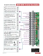
When gate is closed, this input will fully open
gate.
•
When gate is open and auto close timer SW 1,
switch 2 is turned ON, input will re-set and hold
timer.
•
When gate is open and auto close timer SW 1,
switch 2 is turned OFF, input will close gate.
•
When gate is closing, input will reverse gate.
ON
1
2
345678
SW 1
17
Provides 24 VDC, 250 ma. maximum to power
LED. Operation of LED is dependent on setting of
SW 1, switches 4 and 5 (See page 21).
ON
12
3
45
678
SW 1
Operation of relay is dependent on
setting of SW 1, switches 4 and 5.
Relay contacts can be set for Normally
Open (NO) or Normally Closed (NC)
operation.
Contact rating is 1 amp
maximum at 24-volts DC.
ON
12
3
45
678
SW 1
NO
NC
4
•
This input ONLY fuctions when gate is
fully
opened
or in the
closing cycle
.
•
When gate is open:
auto close timer
SW 1,
switch 2 is turned
ON
, input will re-set and hold
timer.
•
When gate is open:
auto close timer
SW 1,
switch 2 is turned
OFF
, input will prevent gate
from closing.
•
When gate is closing: input will
stop
gate when
SW 2, switch 2 is
ON
.
•
When gate is closing: input will
reverse
gate
when SW 2, switch 2 is
OFF
.
ON
1
2
345678
SW 2
ON
1
2
345678
SW 1
Jumper Wire SW 2, switch 2 OFF (Dual Operators only)
Jumper Wire SW 2, switch 2 OFF (Exit Loop Partial Open)
For long gate application. SW 2, switch 3
must be
OFF.
Same operation as #4
terminal above but will only open a closed
gate 14-Ft. or reverse a closing gate to the
14-Ft. open position.
ON
12
3
45678
SW 2
ON
1
2
345678
SW 2
-
Terminal #10 connected to terminal #5 will
PARTIALLY
open
plug-in exit loop detector (Single channel) for a single operator.
-
Terminal #10 connected to terminal #4 will
FULLY
open
bi-parting gates.
Dual operators ONLY using DoorKing’s
plug-in DUAL channel loop detector.
(Page 34).
•
lf SW 2, switch 1 is
ON
, the plug-in exit loop detector
(Single channel) will
FULLY
open the gate (Normal Setting).
Single operator use ONLY
.
•
lf SW 2, switch 1 is
OFF
, the normal exit loop port
function is used by terminal #10:
QUICK GUIDE: Terminal Descriptions
See page 32 for terminal wiring.
UL 325
Terminal
Pages
25-29
24 VAC - 250 mA max.
(See note below)
Terminal #3 Note:
Exceeding 250 mA of power from
this terminal may cause the circuit
board transformer to overheat,
causing intermittent problems.
(See page 32)
3-Button Stop
(Pins 1 & 2 to Enable
NC-Stop Circuit)
FIRE


