MINNY
MINNY
MINNY
MINNY
32
32
32
32
23.5
23.5
23.5
23.5
O
O
O
Oil pressure adjustment
il pressure adjustment
il pressure adjustment
il pressure adjustment
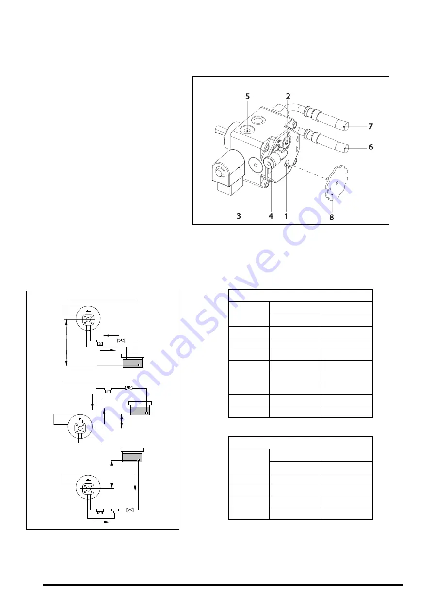
To adjust the oil pump pressure, turn the screw
(1)
(1)
(1)
(1)
clockwise to increase the pressure, and
anticlockwise to decrease it.
1 - Pressure adjustment.
2 - Vacuum gauge point.
3 - Valve.
4 - Manometer point.
5 - Nozzle outlet.
6 - Return.
7 - Intake.
8 – Pressure regulation.
23.6
23.6
23.6
23.6
Oil supply piping diagrams
Oil supply piping diagrams
Oil supply piping diagrams
Oil supply piping diagrams
The diagrams and tables below correspond to installations without reductions and with a perfect
hydraulic seal. It is recommended to use copper pipes. A pressure drop of 0.4 bar (30 cmHg) must
not be exceeded.
Intake installation
Intake installation
Intake installation
Intake installation
H
H
H
H----
Pipe length
Pipe length
Pipe length
Pipe length
(m)
∅
int 8 mm.
∅
int 10 mm.
0,0
34
82
0,5
30
72
1,0
25
62
1,5
21
52
2,0
17
42
2,5
13
32
3,0
9
21
3,5
6
16
Charging installation
Charging installation
Charging installation
Charging installation
H
H
H
H+
+
+
+
Pipe length
Pipe length
Pipe length
Pipe length
(m)
∅
int 8 mm.
∅
int 10 mm.
0,5
36
82
1,0
42
90
1,5
46
100
2,0
50
100
WARNING: Check periodically the flexible pipes conditions. Using kerosene, they have
WARNING: Check periodically the flexible pipes conditions. Using kerosene, they have
WARNING: Check periodically the flexible pipes conditions. Using kerosene, they have
WARNING: Check periodically the flexible pipes conditions. Using kerosene, they have to be
to be
to be
to be
replaced at least every 2 years
replaced at least every 2 years
replaced at least every 2 years
replaced at least every 2 years
Intake installation
Intake installation
Intake installation
Intake installation
H-
Charging installation
Charging installation
Charging installation
Charging installation
H+
H+
DANFOSS
DANFOSS
DANFOSS
DANFOSS ---- MOD. BFP 21 L3
MOD. BFP 21 L3
MOD. BFP 21 L3
MOD. BFP 21 L3


