background image

MINNY

MINNY

MINNY

MINNY    


42

42

42

42    

25

25

25

25


FAIL

FAIL

FAIL

FAILURES

URES

URES

URES    

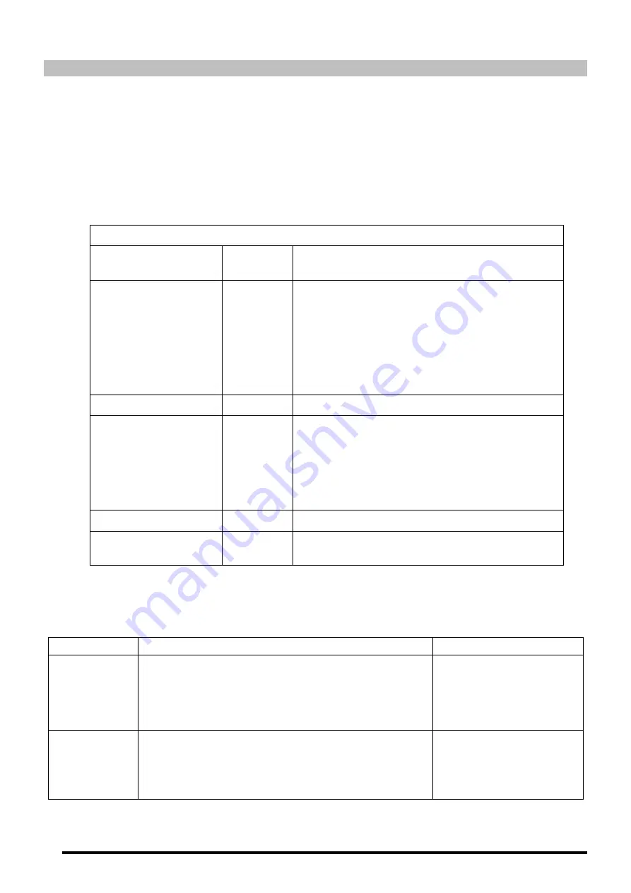
This section provides a list of the most common burner and boiler failures. 

Burner error code

Burner error code

Burner error code

Burner error code    

We  have  already  mentioned  that  the  burner  is  equipped  with  a  cut-out  system,  indicated  by  the 
reset button light. It may cut out accidentally, and in this case the steady red light on this button 
will come on. You may unblock it by pressing the button for approx. 1 second. When the burner is 
blocked and the steady red light is on, visual failure diagnosis may be activated, in accordance with 
the error code table. To enter visual failure diagnosis mode, hold down the reset button for at least 
three seconds.  

Error c

Error c

Error c

Error code table

ode table

ode table

ode table    

Red flashing LED code

Red flashing LED code

Red flashing LED code

Red flashing LED code    

“AL” on 

“AL” on 

“AL” on 

“AL” on 
term. 10

term. 10

term. 10

term. 10    

Possible cause

Possible cause

Possible cause

Possible cause    

Flashes 2 times


On 

No  flame  established  when  ignition  safety  time 
ends. 

- Fuel valves defective or dirty. 

- Flame detector defective or dirty 

- Burner maladjustment, no fuel 

- Ignition unit defective 

Flashes 4 times


On 

External light during burner ignition 

Flashes 7 times


On 

Excessive  flame  loss  during  functioning  (limited 
number of repetitions) 

- Fuel valves defective or dirty 

- Flame detector defective or dirty 

- Burner maladjustment 

Flashes 8 times


On 

Supervision of fuel pre-heater time 

Flashes 10 times


On 

Cabling fault or internal failure, output contacts, 
other failures 

During the failure diagnosis time, the control outputs are disabled and the burner remains off. To 
exit failure diagnosis and activate the burner again, reset the burner control. Hold down the reset 
button for approx. 1 second (<3 s). 

Boiler failures

Boiler failures

Boiler failures

Boiler failures    

FAILURE

FAILURE

FAILURE

FAILURE    

CAUSE

CAUSE

CAUSE

CAUSE    

SOLUTION

SOLUTION

SOLUTION

SOLUTION    

RADIATOR 
DOES NOT 

HEAT UP 

- The pump is not turning 

Unblock the pump 

- Air in hydraulic circuit 

Drain the installation and 
the boiler (the automatic 
air drain valve cap must 
always be loose) 

EXCESSIVE 

NOISE 

- Burner badly adjusted 

Adjust it correctly 

- Flue not correctly sealed 

Eliminate any leaks 

- Flame unstable 

Examine the burner 

- Flue not insulated 

Suitably insulate it 

Содержание MINNY

Страница 1: ...INSTALLATION AND OPERATING INSTRUCTIONS MINNY MINNY MINNY MINNY ...

Страница 2: ... DOMUSA TEKNIK DOMUSA TEKNIK DOMUSA TEKNIK s Authorised Technical Assistance Services Incorrect installation of these boilers could result in damage to people animals or property and the manufacturer will hold no liability in such cases DO DO DO DOMUSA TEKNIK MUSA TEKNIK MUSA TEKNIK MUSA TEKNIK informs all parties concerned that in compliance with section 1 of the first additional provision of Law...

Страница 3: ...CTION 16 9 4 TELEPHONE RELAY CONNECTION 16 9 5 ROOM THERMOSTAT CONNECTION 17 9 6 ANTI LEGIONELLA FUNCTION OPTIONAL WITH HOT WATER TANK ONLY 17 9 7 KEYPAD BLOCK FUNCTION 17 10 E20 REMOTE CONTROL OPTIONAL 18 10 1 FUNCTIONING WITHOUT AN OUTDOOR SENSOR 18 10 2 FUNCTIONING WITH AN EXTERNAL SENSOR OPTIONAL 18 10 3 FUNCTIONING WITH A DHW TANK OPTIONAL 18 10 4 TELEPHONE RELAY FUNCTION 19 11 BOILER SECURIT...

Страница 4: ...8 8 8 8 9 9 9 9 7 7 7 7 4 4 4 4 6 6 6 6 1 1 1 11 1 1 1 5 5 5 5 1 1 1 10 0 0 0 1 1 1 1 Drain valve 2 2 2 2 Domestic sealed oil burner 3 3 3 3 Heating circulating pump 4 4 4 4 Expansion vessel 5 5 5 5 Manual air vent 6 6 6 6 Stainless steel condenser 7 7 7 7 Automatic air vent 8 8 8 8 Safety valve 9 9 9 9 Pressure sensor 10 10 10 10 Thermostat pocket 1 1 1 11 1 1 1 Steel body ...

Страница 5: ... the boiler will switch on or off 1 1 1 16 6 6 6 RESET touch button RESET touch button RESET touch button RESET touch button If the boiler is in lock out mode as the alarm has been triggered touch the RESET button to reset the lock out and restore functioning If you are modifying any of the settings or browsing the user menu you may touch the RESET button to exit the menu WITHOUT SAVING and return...

Страница 6: ... The figure shows the minimum distances for maintenance operations These minimum distances must be respected The boiler is suitable to be installed under a worktop taking into account the minimum distances provided for maintenance operations It should be ensured that said worktop is removable in order to carry out technical assistance and repair operations NOT NOT NOT NOTE E E E If this distance i...

Страница 7: ...OULD NOT be allowed to operate with a return temperature below 30 C IMPORTANT The boiler SHOULD NOT be allowed to operate with a return temperature below 30 C IMPORTANT The boiler SHOULD NOT be allowed to operate with a return temperature below 30 C 3 3 3 3 3 3 3 3 Electri Electri Electri Electrical Connection cal Connection cal Connection cal Connection The boiler is equipped for connection at 23...

Страница 8: ... with Ø80 125 coaxial ducts or Ø80 simple ducts left side and top with Ø80 125 coaxial ducts or Ø80 simple ducts left side and top with Ø80 125 coaxial ducts or Ø80 simple ducts It is recommended that the position at the exhaustion duct exterior portion should be in accordance with the data of the following figures and table Position of the e Position of the e Position of the e Position of the exh...

Страница 9: ...only be those supplied by DOMUSA TEKNIK All flues air intakes and accessories should only be those supplied by DOMUSA TEKNIK All flues air intakes and accessories should only be those supplied by DOMUSA TEKNIK All flues air intakes and accessories should only be those supplied by DOMUSA TEKNIK ...

Страница 10: ...ed for the domestic hot water in the tank This function must be activated by sufficiently qualified personnel The function is enabled by changing the boiler model selectors on the display card inside the control panel Before carrying out any work on the inside of the boiler unplug it from the mains unplug it from the mains unplug it from the mains unplug it from the mains To activate the anti legi...

Страница 11: ...maximum duct length The maximum duct length that can be installed is 12 meters in the Minny 20 model and 10 meters in the Minny 30 model For each horizontal meter the available length is reduced by 2 meters and for each 90º elbow or two 45º elbows it is reduced by 1 m It is recommended that the flue gases outlet pipe be fitted slightly upwardly inclined 2º to 3º thus preventing water and condensat...

Страница 12: ...ightly upwardly inclined 2º to 3º thus preventing water and condensate projections from being ejected outside 1 m Horizontal duct kit 80 125 Stainless steel Cod CGAS000189 1 m Horizontal duct kit 80 125 Polypropylene Cod CGAS000188 Coaxial 90º bend 80 125 Stainless steel Cod CGAS000182 Coaxial 90º bend 80 125 Polypropylene Cod CGAS000080 Coaxial 45º bend 80 125 Stainless steel Cod CGAS000183 Coaxi...

Страница 13: ...ód CGAS000075 Examples of installation 5 5 5 5 FILLING THE INSTALLA FILLING THE INSTALLA FILLING THE INSTALLA FILLING THE INSTALLATION TION TION TION To fill the installation it should be provided with a fill valve which can be used to fill the installation until a pressure of 1 1 5 bars appears on the boiler pressure setting on the display The circuit should be filled slowly and with the automati...

Страница 14: ...temperatures the setpoint temperatures and the pressure of the installation In standby mode the actual boiler temperature in ºC is shown on the display The rest of the available display options can be browsed by touching the MODE button below the display as follows MODE MODE MODE MODE touch button touch button touch button touch button Digital display Digital display Digital display Digital displa...

Страница 15: ... tank Actual boiler pressure measured by the Pressure Sensor 6 6 6 6 Indication of the heating demand status of each circuit connected to the boiler Setpoint of the heating pump speed BC BC BC BC1 1 1 1 The desired display contrast can be adjusted using the touch button on the right of the display 16 16 16 16 ...

Страница 16: ...inny Minny model boilers are condensing boilers In order to obtain maximum boiler performance and energy savings it is therefore recommended to select a setpoint temperature of 55 70 ºC providing this is permitted by the heating system installed and the insulation conditions of your home 7 2 7 2 7 2 7 2 8 2 8 2 8 2 8 2 Selectin Selectin Selectin Selecting the DHW setpoint temperature with hot wate...

Страница 17: ...E E When the heating function is disabled circuit 2 will also be disabled if When the heating function is disabled circuit 2 will also be disabled if When the heating function is disabled circuit 2 will also be disabled if When the heating function is disabled circuit 2 will also be disabled if it is connected it is connected it is connected it is connected 8 2 8 2 8 2 8 2 Functioning with a domes...

Страница 18: ...from seizing up if they have been out of use for a long period This system remains enabled while the boiler is plugged into the mains 9 2 9 2 9 2 9 2 Anti Anti Anti Anti frost function frost function frost function frost function This function protects the boiler from freezing up during cold weather If the boiler temperature drops to below 6 ºC the heating circulation pump will start up If the boi...

Страница 19: ...an l with hot water tan l with hot water tan l with hot water tank only k only k only k only This optional function prevents the bacteria causing legionnaire s disease from proliferating in the hot water accumulated in the tank Every 7 days the temperature of the water in the tank is raised to 70 ºC to kill any such bacteria This function will only run if the boiler is left switched on The boiler ...

Страница 20: ...an outdoor sensor Conventional heating installation direct circuit Conventional heating installation direct circuit Conventional heating installation direct circuit Conventional heating installation direct circuit The maximum temperature for heating circuit Nº1 the scheduled heating times and the desired room temperatures can be selected on the remote control The E20 remote control will calculate ...

Страница 21: ...ed with the E20 remote control 10 4 10 4 10 4 10 4 Telephone relay function Telephone relay function Telephone relay function Telephone relay function The E20 remote control is designed for connection to an external telephone relay If a telephone relay is connected to the E20 remote control the heating mode of heating circuit Nº1 and the DHW mode can be switched on and off from anywhere in the wor...

Страница 22: ...o flash on the digital display 12 12 12 12 The burner will switch off and stop heating the installation This occurs when the boiler exceeds a temperature of 110 ºC To unblock it wait until the boiler drops to below 100ºC and press the button on the safety thermostat located inside the boiler on the underside of the electrical box after first having removed the button cover 11 2 11 2 11 2 11 2 Burn...

Страница 23: ...14 14 FIRST STAR FIRST STAR FIRST STAR FIRST START T T T UP UP UP UP For the guarantee guarantee guarantee guarantee to be valid to be valid to be valid to be valid the boiler must be started up for the first time by an official DOMUSA official DOMUSA official DOMUSA official DOMUSA TEKNIK Technical Assi TEKNIK Technical Assi TEKNIK Technical Assi TEKNIK Technical Assistance Service stance Service...

Страница 24: ...s are functioning correctly For correct cleaning the following recommendations should be carefully observed Cleaning the boiler body Cleaning the boiler body Cleaning the boiler body Cleaning the boiler body Open and remove the outer door of the boiler Remove the burner 2 2 2 2 by unscrewing the fixing nut on the top of the burner Remove the combustion chamber door and the exhaustion duct cover un...

Страница 25: ...and leaving it empty draining all the water and leaving it empty draining all the water and leaving it empty draining all the water and leaving it empty 16 3 16 3 16 3 16 3 Boiler water characteristics Boiler water characteristics Boiler water characteristics Boiler water characteristics In areas with water hardness of over 25 30ºF treated water must be used in the heating installation to avoid an...

Страница 26: ...sumption at full load elmax kW 0 217 Auxiliary electricity consumption at part load elmin kW 0 077 Auxiliary electricity consumption in standby mode PSB kW 0 002 Standby heat loss Pstby kW 0 1 Emissions of nitrogen oxides NOx mg kWh 110 Heating temperature adjustment ºC OFF 30 85 Maximum safety temperature ºC 110 Maximum pressure for heating mode bar 3 Heating expansion vessel capacity Lts 8 8 Hea...

Страница 27: ...lue changes After selecting the desired speed touch the ON touch button to record the value and exit the parameter UB UB UB UB WARNING WARNING WARNING WARNING Any interference in the operation and installation of the heating circuit must be done Any interference in the operation and installation of the heating circuit must be done Any interference in the operation and installation of the heating c...

Страница 28: ... MENTS MENTS MENTS 845 400 600 183 383 529 613 673 762 183 383 529 614 674 757 SC IC IC RC VS SH SC IC IC RC VS SH 220 92 120 40 35 IC IC IC IC Heating outlet 1 H IC IC IC IC Optional heating outlet 1 H RC RC RC RC Heating return 1 H VS VS VS VS Safety valve SC SC SC SC Condensation water outlet SH SH SH SH Fume exhaustion duct Ø80 Ø125 ...

Страница 29: ...should be two should be two should be two should be two wire wire wire wire VOL VOL VOL VOLT FREE T FREE T FREE T FREE ro ro ro room stat om stat om stat om stat L L L L Line N N N N Neutral bc7 bc7 bc7 bc7 Burner terminal n 7 Q Q Q Q Burner BV BV BV BV DHW charge pump BC BC BC BC1 1 1 1 Heating circuit N 1 circulating pump BC BC BC BC2 2 2 2 Heating circuit N 2 circulating pump E20 E20 E20 E20 Re...

Страница 30: ...splay Card splay Card splay Card splay Card J8 J8 J8 J8 S S S S2 2 2 2 ON ON ON ON 1 1 1 1 2 2 2 2 3 3 3 3 4 4 4 4 ON ON ON ON S S S S1 1 1 1 1 1 1 1 2 2 2 2 TH TH TH TH C C C C 2 2 2 2 1 1 1 1 Black White Pink TS TS TS TS C C C C 2 2 2 2 1 1 1 1 Black Red Pink TS TS TS TS Security thermostat TH TH TH TH Fumes thermostat SP SP SP SP Pressure sensor R R R R Phone relay J6 J6 J6 J6 Phone relay conne...

Страница 31: ...nce service Burner The burner has cut out To unblock it press the illuminated button on the burner 2 2 2 2 This alarm is set off when there is a functioning anomaly in the burner or the fuel installation If this alarm occurs repeatedly you should contact the nearest official technical assistance service Boiler sensor The boiler sensor 4 4 4 4 is damaged or disconnected Contact your nearest officia...

Страница 32: ...er annually he maintenance of the filter annually he maintenance of the filter annually he maintenance of the filter annually 23 3 23 3 23 3 23 3 Burner start Burner start Burner start Burner start up up up up Ensure there is fuel in the tank that the oil valves are open and that there is an electric connection to the burner Turn on the master switch Unscrew the air bleed screw manometer point The...

Страница 33: ...ne loosen the combustion line blocking screw BL BL BL BL Turn the line regulator RL RL RL RL clockwise to increase the airflow and anticlockwise to decrease it After adjustment tighten the combustion line blocking screw BL BL BL BL BL RL 3 mm 0 1 Correct position of electrodes Correct position of electrodes Correct position of electrodes Correct position of electrodes To ensure correct ignition of...

Страница 34: ... Pipe length m int 8 mm int 10 mm 0 0 34 82 0 5 30 72 1 0 25 62 1 5 21 52 2 0 17 42 2 5 13 32 3 0 9 21 3 5 6 16 Charging installation Charging installation Charging installation Charging installation H H H H Pipe length Pipe length Pipe length Pipe length m int 8 mm int 10 mm 0 5 36 82 1 0 42 90 1 5 46 100 2 0 50 100 WARNING Check periodically the flexible pipes conditions Using kerosene they have...

Страница 35: ...t Electric current Electric current 220 V 50 Hz 23 8 23 8 23 8 23 8 Nozzles Nozzles Nozzles Nozzles Minny Minny Minny Minny boilers are supplied with the burner fitted together with its corresponding nozzle and a standard pre adjustment The following table shows the nozzles and adjustments for each particular model MODEL MODEL MODEL MODEL Nozzle Nozzle Nozzle Nozzle Pump pressure Pump pressure Pum...

Страница 36: ...rmer MB MB MB MB Oil Pump Motor EV EV EV EV Valve RP RP RP RP Pre heater resistance L L L L Live N N N N Neutral TP TP TP TP Pre heater thermostat 23 10 23 10 23 10 23 10 Quick connector Quick connector Quick connector Quick connector To connect and disconnect the red oil intake tube to the nozzle proceed as follows Press the connector ring in the direction of the arrow pulling on the red tube at ...

Страница 37: ...esetting the burner control and activating deactivating the diagnosis functions The multi colour LED on the reset button is the indicator for visual diagnosis The button and the LED are located under the transparent cover of the reset button During normal functioning the various operating statuses are indicated in the form of colour codes see the colour code table below During ignition the indicat...

Страница 38: ...13 SAIS000215 Right panel insulation 2 2 2 2 SAIS000213 Top panel insulation 14 14 14 14 SEXT000304 Right locking 3 3 3 3 SEPO002850 Rear panel 15 15 15 15 CFER000058 Condensing pot cleaning brush 4 4 4 4 SAIS000212 Rear panel insulation 16 16 16 16 SELEMIN000 Electrical main board 5 5 5 5 SAIS000214 Left panel insulation 17 17 17 17 SEXT000237 Door 6 6 6 6 SEXT000240 Left panel 18 18 18 18 SQUEMI...

Страница 39: ... CFER000313 Clamp 2 2 2 2 CFOV000185 Hose 13 13 13 13 CFER000311 Siphon hose 3 3 3 3 CFOV000034 Manual air vent 14 14 14 14 SCOB012838 Heating pipe 4 4 4 4 SCON001705 Expansion vessel 8L 15 15 15 15 SPIN000008 Bracket 5 5 5 5 CVAL000004 Safety valve 16 16 16 16 CTOR000198 M5 nut 6 6 6 6 CELC000252 Pressure sensor 17 17 17 17 CFOL000114 1 cap 7 7 7 7 SCOB012839 Pump pipe 18 18 18 18 CFOV000182 1 Jo...

Страница 40: ... 1 1 1 1 CTOR000073 Screw 10 10 10 10 CFOL000031 1 2 nut 2 2 2 2 SCON001704 Aix box cover 11 11 11 11 CFER000305 Ø10 cap 3 3 3 3 CTOR000089 M4 nut 12 12 12 12 SCHA012163 Baffle 1 unit 4 4 4 4 SEPO002918 Air box RCHAMIN000 Baffle 8 units 5 5 5 5 CGAS000387 Gas exhaust Ø80 13 13 13 13 CAIS000019 Condesing pot cover gasket 6 6 6 6 SAIS000210 Condensing pot insulation 14 14 14 14 SCHA012139 Condesing ...

Страница 41: ...Door insulation 2 2 2 2 CTOR000039 M10 nut 12 12 12 12 SCON001776 Comb Chamber door 3 3 3 3 SCON001777 Comb gas manifold 13 13 13 13 SCHA011901 Expansion vessel support 4 4 4 4 SAIS000217 Manifold gasket 14 14 14 14 CTOR000039 M10 nut 5 5 5 5 SAIS000209 Body insulation 15 15 15 15 CFOV000158 3 4 Joint 6 6 6 6 RCHAMIN001 Boiler body 16 16 16 16 COTR000010 Viewport glass 7 7 7 7 SCOB012844 Sensor ho...

Страница 42: ...Code Name Name Name Name 1 1 1 1 RMIN000000 Electrical board cover and glass 2 2 2 2 CELC000360 Electric display board 3 3 3 3 CELC000255 Pressure transducer connection cable 4 4 4 4 CELC000298 Communication cable 5 5 5 5 CELC000358 Electric main board 6 6 6 6 CELC000022 Safety thermostat 110º 7 7 7 7 CELC000022 Safety thermostat 110º 8 8 8 8 CELC000234 PTC Sensor 9 9 9 9 CELC000036 Weidmuller 3 p...

Страница 43: ...QUE000089 Electrovalve coil 6 6 6 6 CQUE000155 Turbulator disc 25 25 25 25 CQUE000124 Electrovalve cable 7 7 7 7 CQUE000019 Ignition electrodes 2 2 2 26 6 6 6 CTOE000065 Counter thread interior stoop 8 8 8 8 CQUE000044 Burnen fan 2 2 2 27 7 7 7 CQUE000004 Coupling between motor and pump 9 9 9 9 SEPO001255 Air adjustment support 2 2 2 28 8 8 8 CQUE000102 Motor 10 10 10 10 CTOE000064 Air adjustment ...

Страница 44: ...nition safety time ends Fuel valves defective or dirty Flame detector defective or dirty Burner maladjustment no fuel Ignition unit defective Flashes 4 times On External light during burner ignition Flashes 7 times On Excessive flame loss during functioning limited number of repetitions Fuel valves defective or dirty Flame detector defective or dirty Burner maladjustment Flashes 8 times On Supervi...

Страница 45: ...p again automatically once the error has been solved 1 Low voltage U 160 V or Excess voltage U 253 V 1 Check the power supply 195 V U 253 V 2 Excess temperature of the module the temperature of the motor is too high 2 Check the room temperature and that of the fluid Flashes red The pump is out of order The pump is stopped blocked La bomba no arranca de nuevo automáticamente Cambie la bomba Para su...

Страница 46: ...MINNY MINNY MINNY MINNY 44 44 44 44 NOT NOT NOT NOTE E E ES S S S ...

Страница 47: ...45 45 45 45 NOT NOT NOT NOTE E E ES S S S ...

Страница 48: ... 95 San Esteban auzoa z g 20730 AZPEITIA 20737 ERREZILL Gipuzkoa Telfs 34 943 813 899 ww ww ww www domusateknik com w domusateknik com w domusateknik com w domusateknik com DOMUSA TEKN DOMUSA TEKN DOMUSA TEKN DOMUSA TEKNIK IK IK IK reserves the right to make modifications of any kind to its product characteristics without prior notice CDOC001955 CDOC001955 09 19 ...

Отзывы: