DoAll DS-320SA Скачать руководство пользователя страница 50

DS-320SA 


Instruction Manual 

- 50 -


www.doallsaws.com


12.2


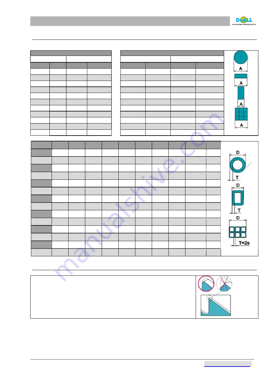
HOW TO CHOOSE THE RIGHT TEETH FOR CUTTING  

The table for choosing saw-blade is attached to the machine. 


CONSTANT


VARIABLE


CONSTANT


VARIABLE


teeth 

teeth 


teeth 

teeth 

  -0,25 

22 

    -0,8  

6/10 


-0,6 

14 

- 0,6 

10/14 

  0,25-0,4 

18 

0,8-1,6 

5/8 


0,6-1,6 

10 

0,6 – 1,6 

8/12 

0,4-0,8 

14 

1,6-3,2 

4/6 


1-2 

1 – 2 

6/10 

0,8-1,2 

10 

  3,2-6,5 

3/4 


1,4-2,8 

6** 

1,4 – 2,8 

5/8 

1,2-2 

6,5-8 

2/3 


1,6-3,2 

4** 

1,6 – 3,2 

5/6 

2-3,2 

8-16 

1,4/2 


2-4,7 

3** 

2 – 4,7 

4/6 *  ** 

  3,2-4,8 

16-25 

1/1,3 


3,2-7 

3,2 – 7 

3/4 *  ** 

4,8-8 

> 25 

0,75/1,25   

5-14 

1,25 

5 – 14 

2/3 

8-16 


6-18 

0,75 

6 – 18 

1,5/2 

16-32 

1,25   


8-24 


8 – 24 

1,1/1,6 

> 32 

0,75   


>20 


> 20 

0,75/1,25 

tab. 12-1 

T/D 

0,8 

1,6 

2,4 

3,2 

4,8 

12 

20 


0,08 

14 

10/14 

10/14 

10/14 

10/14 

8/12 

8/12 

8/12 

8/12 

5/8 

0,12 

14 

10/14 

10/14 

8/12 

8/12 

8/12 

8/12 

6/10 

6/10 

5/8 

0,16 

10/14 

10/14 

8/12 

8/12 

8/12 

6/10 

6/10 

5/8 

5/8 

4/6 S 

0,2 

10/14 

10/14 

8/12 

8/12 

6/10 

6/10 

5/8 

4/6 S 

4/6 S 

4/6 S 

0,24 

10/14 

8/12 

8/12 

6/10 

6/10 

5/8 

5/8 

4/6 S 

4/6 S 

4/6 S 

0,32 

10/14 

8/12 

8/12 

6/10 

5/8 

5/8 

4/6 

4/6 

4/6 

4/6 

0,4 


8/12 

6/10 

5/8 

4/6 

4/6 

4/6 

4/6 

4/6 

4/5 

0,5 


8/12 

6/10 

4/6 

4/6 

4/6 

4/6 

4/6 

4/6 

4/5 

0,6 


8/12 

6/10 

4/6 

4/6 

4/6 

4/6 

4/5 

4/5 

4/5 

0,8 


4/6 

4/6 

4/6 

4/6 

4/6 

4/5 

4/5 

3/4 

1,2 


4/6 

4/6 

4/5 

4/5 

4/5 

4/5 

2/3 


4/5 

3/4 

2/3 

2/3 


3/4 

2/3 

2/3 

> 4 


2/3 

1,5/2 

tab. 12-2 

12.3


RUN IN OF SAW-BLADE - WHEN HAVING A NEW SAW-BLADE                        

 
Run  in  is  necessary 

for  achieving  max.  saw-blade  life  cycle.  By  running  in 

you prevent breaking microfragments   of teeth, that damage other teeth and 
increase stress to the saw-blade.  
Let  saw-blade  run  on  no-load  for  about  30  seconds  with  the  coolant  pump 
working ( due to right lubrication of saw-blade). Run in do if possible with easy 
machined  materials  by  min.  speed  of  arm  when  cutting.  After  about  30 
minutes increase the speed of feed continuously.


Содержание DS-320SA

Страница 1: ...INSTRUCTION MANUAL BAND SAW MACHINES TYPE DS 320SA Version II generation version 2 DoALL Sawing Products 800 321 9913 5505 West 123rd Street Minneapolis MN 55378 www doallsaws com...

Страница 2: ...5 5 IT IS PROHIBITED TO 17 5 6 SAFETY REGULATIONS 18 5 6 1 SAFETY COMPONENTS 19 5 7 DESCRIPTION OF LABELS 20 6 INSTRUCTIONS FOR TRANSPORT 22 7 DIRECTIVES FOR STORAGE 22 8 MACHINE INSTALLATION 23 8 1...

Страница 3: ...ARM MOVEMENT WHEN CUTTING 51 12 5 1 EXTRA ACCESSORIES 52 12 6 MINI LUBE 54 5 5 1 SETTING AND ADJUSTMENT 54 12 6 1 CONTROL 54 12 7 HYDRAULICAL UPPER VICE 55 12 7 1 UPPER THRUST SETTING 55 12 7 2 CONTR...

Страница 4: ...grips the material and the saw starts working The cutting speed of the arm is controlled by a throttle valve Arm and vice movements after cut following set users parameters The vice opens and the oper...

Страница 5: ...the groove with the spring General angles are adjusted by the nonius It is possible to equip the machine by reading of angle by 2 4 STANDARD EQUIPMENT The blade leading in guides with hardmetal plate...

Страница 6: ...DS 320SA Instruction Manual 6 www doallsaws com 2 5 1 SET OF TOOLS FOR COMMON SERVICE Item Descritpion 1 Allen wrenches 2 Allen wrench for blade tightenns 3 Wrenchs pic 2 1...

Страница 7: ...lowing ambient effects AA5 ambient temperature 40 to 105 F AB5 relative humidity up to 95 AC1 AD1 negligible presence of water AE1 AF1 AG2 AH2 AK1 AL1 AM negligable effects AN1 AP1 AQ1 AR1 AS1 BA4 onl...

Страница 8: ...7 9 10 6 X X D in 7 08 4 3 3 2 4 3 X X axb in 12 6x11 8 11 4x11 8 7 5x7 5 10 6x7 9 X 12 6x6 3 tab 3 2 recommended values the shortest cutting in 0 11 the smallest divisible diameter in 0 2 the shorte...

Страница 9: ...tic oil filled in the gearboxes it is not necessary to make any service or filling the oil during average 15 000 hours of lifetime Oil for MINI LUBE 0 5 l 0 53qt tab 3 7 3 5 EMISSIONS MACHINE NOISE LE...

Страница 10: ...itten in the spaces provided above This information is printed on a label attached to your machine Be sure to provide machine model and serial numbers with any correspondence or parts orders Specifica...

Страница 11: ...rm position 11 Measuring end stop 12 Metalic gutter vessel for chips 13 Turn table of the machine It carries the arm and enables its turning 14 Anchoring holes 15 Hydraulic centrale 16 Main power supp...

Страница 12: ...and release the trapese seminut it is possible to move with the jaw according to your needs 4 Locking lever for the vice position right left When changing the position of the vice it is necessary to l...

Страница 13: ...aning brush 5 Drive pulley 6 Adjustable guide of the saw band Washed by coolant 7 Band tensioning 8 Locking lever of the adjustable guide 9 Three phase electric motor see the Drive Information 10 Hydr...

Страница 14: ...www doallsaws com 4 3 HYDRAULIC UNIT pic 4 4 1 Motor 2 Pressure regulation screw 3 Pressure gage of the main hydraulic circuit 4 Oil plug 5 Reservoir oil 6 Drain plug 7 Hydraulic valve main vice 8 Hyd...

Страница 15: ...STOP button immediately and TURN OFF THE MAIN SWITCH 19 Stay clear of machine while in operation 20 Use only recommended bands or blades 21 Use a conveyor system to safely support long bars in front a...

Страница 16: ...e following risks 5 2 1 MECHANICAL RISK The danger of finger hand bruising or leg bruising when dismantling parts of machines Danger of injuries caused by dismantled parts dropping when doing maintena...

Страница 17: ...ng electrical qualification After connection he inspects the correct operation of the machine including the guards and safety disconnection and blocking It is the employer s responsibility to have a l...

Страница 18: ...ay behind the protective line during cutting cutting it means that blade moves The protective line is determined by the area in front of control panel Machine surroundings contour line copying the gro...

Страница 19: ...P button the controlling circuits are still charged with electric current Press the EMERGENCY STOP button immediately in case of any failure or possible danger To release or reset the EMERGENCY STOP b...

Страница 20: ...safety sensors 5 7 DESCRIPTION OF LABELS Clamping of material to vice During machine operation keep unauthorized personnel out of the work zone Make sure the vice jaws have firmly clamped the materia...

Страница 21: ...his be very careful Adjustment label MAX the highest value speed force pressure MIN the lowest value Wear eye protection protective glasses or face shield when manipulating with saw blade when manipul...

Страница 22: ...ice pic 6 1 When transporting the equipment on a truck use nylon ropes to fastened the machine down in the loading area pic 6 2 WARNING The customer is totally responsible for the product shipment cos...

Страница 23: ...foundation is essential for normal machine operation The machine must be installed in a location that satisfies all of its foundation requirements After the customer decides where to install the machi...

Страница 24: ...s of metal with minimum 0 4 inches thickess under the stand screws Check the plane with the scale on the table Machine has to be leveled in both longitudinal and diagonal directions After the accurate...

Страница 25: ...vel the conveyors with the plane of machine plane defined by tangents of supporting rollers eventually by plane of the table The machine won t be cutting straight the lifespan of the blade vices and h...

Страница 26: ...ded base marked green The socket circuit for connection of the machine or the circuit for the power network where the saw will be connected must be carried out according to the valid regulations and t...

Страница 27: ...he operator turns off the machine using Emergency Stop button while the blade is rotating it is essential to wait one minute for the frequency converter memory to reset Turn off main switch wait for 1...

Страница 28: ...sure nobody can to be injured by the Machine bow BEFORE the button pressing CAUTION To prevent equipment damage the operator must stop the arm going down before the blade touches the material If unabl...

Страница 29: ...TING SCREEN pic 9 3 Item Description 1 MENU button This is where all the user and service parameter settings can be accessed see next section 2 Cycle cut indication 3 BRP indication this is activated...

Страница 30: ...technician access under service password 5 Input function control only for authorized personnel service technician access under service password 6 Setting the levels for measurement 7 Service paramete...

Страница 31: ...ttings Par 4 Function of the band at the end of the cut Setting the band motion at the cut end 0 the band will stop in the bottom position 1 the band will stop only after reaching the top position Def...

Страница 32: ...only if the arm height measuring function is active The position reached by the arm when moving up after finishing the cut is thereby set Par 9 User down limit position in User setting of the bottom a...

Страница 33: ...e changing or error message W003 bleaking or loosing the blade Machines with hydraulic blade tightening which have service mode It is possible to handle with machine by following screen buttons even t...

Страница 34: ...sonnel at DoALL All screws of the hydraulic system must be well tightened Use two spanners for tightening the screws one is for socket one is for nut To prevent the unpainted surfaces on the machine f...

Страница 35: ...in switch to position 1 pos 5 3 If the saw was turned off with EMERGENCY STOP button pos 4 unlock the EMERGENCY STOP button by turning it to the right With this the machine is prepared for cutting 4 S...

Страница 36: ...y a aretation lever No 5 9 7 2 CUTTING OF THE LEFT ANGLE CUTS lift the arm to its upper position above the firm position of the vice readjust the vice by lever No 4 situated under the vice release the...

Страница 37: ...TAL POINTER OF THE ANGLE ACCESSORIES The angle is indicated by the digital pointer on the panel pic 9 11 Item Description 16 Actual turn table position Not standard equipment 17 RTO angle is set as th...

Страница 38: ...PP V9 arresting hole WARNING The saw does not work unless the arm is not located above the upper operational position WARNING In case the frame is above the top working position or just below it the s...

Страница 39: ...There is the rule that the blades should be supported on both sides as close the material as possible Supporting is ensured by guides Position of the movable guide is determined by the width of the c...

Страница 40: ...nto water while stirring it continuously All necessary information is printed on the canister or in the accompanying documents 9 12 HOW TO SET THE ADJUSTABLE END STOP 1 Loose the safety screw pos 1 pi...

Страница 41: ...grips and the arm moves to a position above the material Set the cutting speed of the arm with the throttle valve The saw cuts through the material by following the set parameters The vice is under p...

Страница 42: ...G after breaking a communication with frequency converter an error number and description appears at the top of the screen pic 10 4 At resolving the system error it is necessary to restart the freque...

Страница 43: ...320SA Instruction Manual 43 www doallsaws com pic 10 6 Press to restart the converter If the system error is cleared the display stops blinking in red The machine returns to normal operation Return us...

Страница 44: ...coolant sufficient amount of the oil in the water and sufficient amount of coolant running into the cut 7 the precision of the leading of the blade in guides the demand for the minimal clearance of g...

Страница 45: ...THE SAW BAND The band is correctly tensioned when the light on the control panel is active The band is tensioned by tightening tensioning screw A on the front part of the saw arm After turning on the...

Страница 46: ...oning screw No 1 3 After uncovering the band guard No 3 and the locking lever No 4 remove the band from the safety clips No 5 Remove the band from pulleys No 6 and from the guides No 1 7 4 Always chec...

Страница 47: ...position tighten the tightening screws by tightening of the adjustable screws set the clearance between the leading desks to the value 0 037 in the clearance between the blade and leading desks check...

Страница 48: ...heck the cleeaning brush and its position to blade teeth The right position of the cleaning brush towards the blade set by screws pos 1 1 1 Loosen the safety screw pos 1 2 Replace the worn out brush w...

Страница 49: ...gap causes gradual wedging of the chip in the cut the loss of quality of the cut and enormous increase of the cutting resistance and input of the machine The claim of damage of pulley bearings gear b...

Страница 50: ...6 10 5 8 0 16 10 14 10 14 8 12 8 12 8 12 6 10 6 10 5 8 5 8 4 6 S 0 2 10 14 10 14 8 12 8 12 6 10 6 10 5 8 4 6 S 4 6 S 4 6 S 0 24 10 14 8 12 8 12 6 10 6 10 5 8 5 8 4 6 S 4 6 S 4 6 S 0 32 10 14 8 12 8 12...

Страница 51: ...the bandsaw helps you with the setting of the right speed of arm movement when cutting A B C a thin or broken chips increase the speed of feed or reduce the speed of a blade b thick or blue chips redu...

Страница 52: ...end stop which is mounted directly to the machine length 1m ST 240 CK Cleaning brush of blade driven passively driven by sawing blade ST BRP Electronical regulation of the down shift ST 300 DPP Autom...

Страница 53: ...cylinder length 390 mm with the bearing for RD roller coneyor The capacity of roller table increased from 200 kg m to 400 kg m O RB 200 Side vertical fix cylinder height 200 mm monted on the RD table...

Страница 54: ...of the tool b Install the mini lube on the stationary part of the machine c Connect pressurised air 1 with the inlet screw coupling The min operational pressure is 6 Atm d Connect the connector of pr...

Страница 55: ...aw of the vice 8 Basic thrust jaw A or B type type A 130mm type B 250mm 9 Mounting screws of replaceable thrust jaw 10 Replaceable thrust jaw A or B type type A 130mm type B 250mm 11 Quickclamps 12 Pl...

Страница 56: ...ith upper clamping not to damage hydraulic pipes It is necessary to fix hydraulic pipes to the firm or movable part of machine Pipes must be protected against mechanical damage against high temperatur...

Страница 57: ...which is included as the part of this type of roller table In case you would connect roller table RD directly to the machine the angle cutting would be disabled connecting part 290 LR PR is not a par...

Страница 58: ...DS 320SA Instruction Manual 58 www doallsaws com Connection of the roller table on input before the cutting zone pic 12 4 pic 12 5...

Страница 59: ...DS 320SA Instruction Manual 59 www doallsaws com Connection of the roller table on output after the cutting zone pic 12 6 pic 12 7...

Страница 60: ...he horizontal level of the saw i e level determined by the tangent of the support rollers If the routes are not in alignment the material will be undercut the saw band will not reach its maximum life...

Страница 61: ...for wear replace the band if necessary WEEKLY If the hydraulic or gear oil does not extrudes see the regulations for changing the fillings In other case order DoALL service To clean and oil all movab...

Страница 62: ...device Apply plastic lubricant onto the device weekly E 3 Trapezial screw of the movable jaw of the vice To clean the screw threads Put oil into the thread weekly F 4 Position of the joint shaft Appl...

Страница 63: ...e technician of DoALL company and check the completeness and correctness of the notice The change of oil must be provable Specification Recommended fillings Alternatives Oil Change Intervals A Hydraul...

Страница 64: ...instructions Recycle used oil Contact a recycling facility to have the oil recycled properly to protect the environment Do not dump the oil on land or dispose of it in waterways 13 5 FILLING AND CHANG...

Страница 65: ...the coolant and repair the leaking of hydraulic of gear oils immediately Contact a recycling facility to have the coolant recycled properly to protect the environment Do not dump the coolant on land...

Страница 66: ...d is dragged downwards by the guides Pos B or upwards by the sawn material Pos C it means that it is not correctly guided and the guides should be adjusted The position of the guides can be adjusted b...

Страница 67: ...EEN THE SAW BAND AND CARBIDE PADS Adjustments of clearance between the belt and the guide plates are made Loosen the screw A insert a 0 037in thick plate between the guide plates and then tighten the...

Страница 68: ...d Before you start adjusting the position of the tensioning pulley check that all screws which might affect the axial position of the driving and tensioning pulleys have been tightened Also inspect th...

Страница 69: ...o the size and weight of the material the lower the pressure the longer the life of mechanical parts of the vice 14 5 SETTING PRESSURES The pressures are pre set in the factory we strictly recommend n...

Страница 70: ...oupling Pos 1 and the spacer Pos 2 Use a slide gauge Pos 5 to measure the coupling s position against the motor flange Install a new coupling or motor into the same position If there were no clearance...

Страница 71: ...DS 320SA Instruction Manual 71 www doallsaws com pic 14 3...

Страница 72: ...burned or damaged 4 el source is not correct 5 gearbox is blocked nylon clutch wheels of the gear box shaft seating 6 fuses in a primary circuit 7 fuses in a control panel 8 transformer is damaged or...

Страница 73: ...machine For Sales Parts and Service call 1 888 362 5572 For a complete machine inspection schedule a service appointment with a DoALL service technician For additional information when the customer e...

Отзывы: