background image

17 


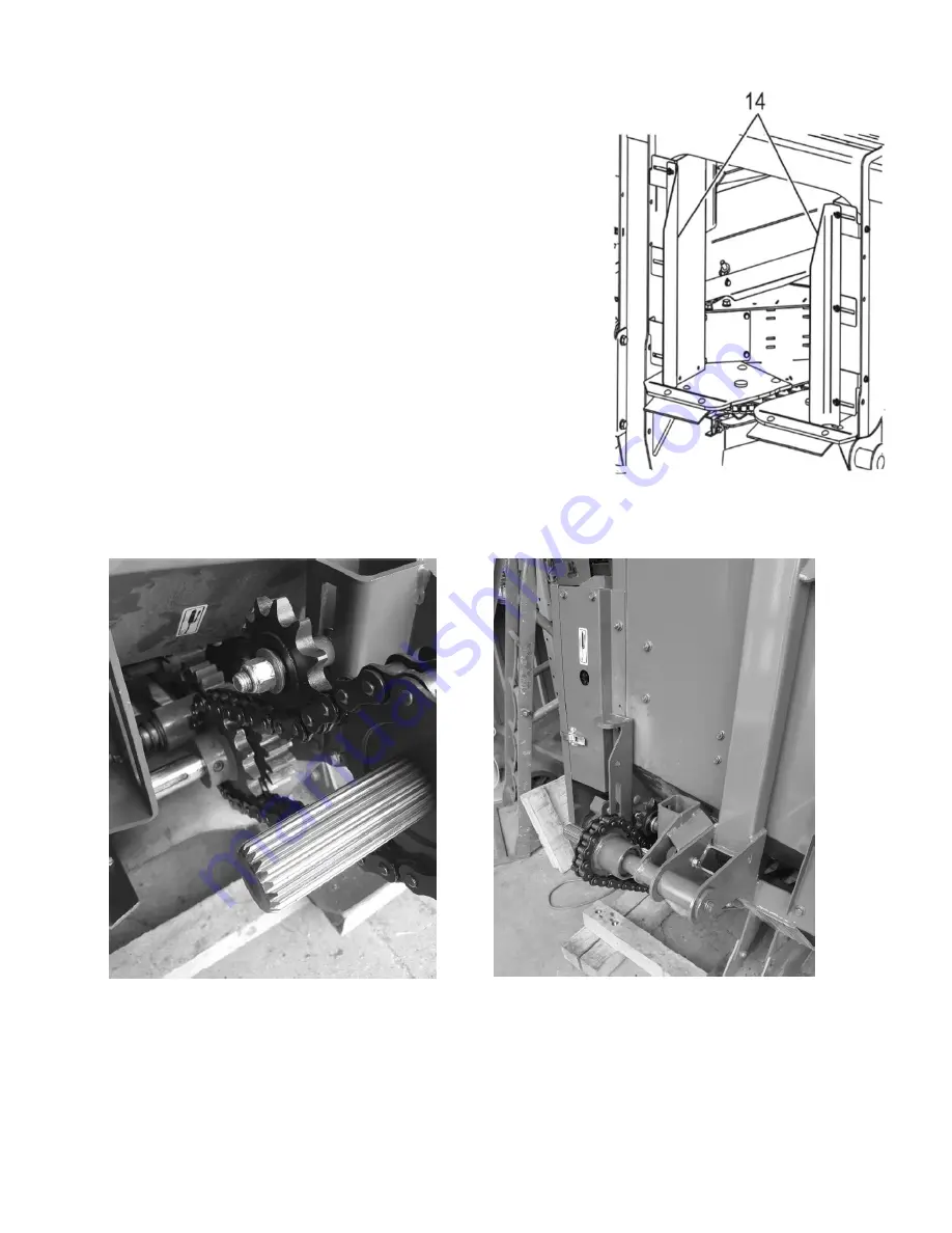
Adjust feed roll throat guards when mated to the harvester (#14


Test the corn header on the harvester to ensure drive and 
suspension functionality 


Clean & polish headers 


For a Scorpion 300 and 2430 models no drive kit is required to install on the hay pick-up.  


For the Scorpion 350, a special drive kit is required for the hay pick up. An installation guide is provided. 


Test ALL headers on the harvester to ensure drive and suspension functionality 


Hay / corn crop conversion on the harvester depending on crop to harvest (See operator’s manual) 


Содержание Scorpion 2430

Страница 1: ...1 Setup PDI Guide Manual no F6920T020 v1 0 Scorpion 300 2430 Scorpion 350 Stinger ...

Страница 2: ...ut prior notice Safety The Safety section of your Operator s manual is intended to point out some of the basic safety situations which may be encountered during normal operation and maintenance of your Forage Harvester and to suggest possible ways of dealing with those situations This section is NOT a replacement for other safety practices featured in other sections of this guide The safety of the...

Страница 3: ...n and or hay Drive kit for respective header Validate the model of each unit Serial number Cutterhead transmission LOC range etc Processor PTO Drawbar size etc Take note and notify us if there is a problem Any breakage damage and missing parts must be reported to DION Ag within 5 days The delivery waybill must be signed and noted to identify any damage upon reception Failure to do so will void the...

Страница 4: ...re 2 slots on the harvester frame for the forks One perpendicular to the axle and one at a 45 angle Approach the harvester perpendicular to the frame and axle mount Advance the forklift through the 2 fork slots until the forks are sufficiently under the pick up point Fork pick up point under the harvester frame ...

Страница 5: ...s and the processor assembly NEVER place the harvester directly on the ground Ensure the harvester is properly supported on blocks with a minimum height of 6 15cm at 3 points as described 1 point under the left axle 1 point under the right header attachment location 1 point at the tongue supported by a block of wood OR the jack stand which the harvester is equipped with Kernel processor assembly F...

Страница 6: ... in trailed mode as shown Position the axles flat on wooden blocks and remove the wheel bolts Place the wheels onto the axles ensuring the air valves face upwards Use a tire lifting tool OR two people to place the tire onto the axle Install the 6 bolts by hand Tighten the 6 bolts to 120lb ft 163 N m Wheel torque should be check after the first hour and every 20h for the first 60h Repeat for all wh...

Страница 7: ...ed to approximately 18 between the ground and the frame The longer portion of the axle should be towards the rear of the harvester Use the lock pin and cotter pin in the toolbox to fix the axle to 1 of the 3 desired position 3 holes in the long tube Typically the axle should be installed with no holes exposed axle tube assembly as close to the harvester as possible Approach the harvester perpendic...

Страница 8: ...ock washers from the axle assembly Lift the tandem wheel assembly Ensure the longer portion of the assembly faces the front of the harvester Mate the axle assembly to the hub on the harvester and install the lock washers and nuts by hand Tighten the 8 nuts ensuring the carriage bolts remain properly seated Lift the harvester and remove blocks Longer portion of the axle towards the front ...

Страница 9: ...steners for the light assembly Pull the cable through the opening Use the cable ties in the toolbox to affix the cable to the arm Place the connector as shown and loop any excess cable Insert the light assembly through the opening Fasten the assembly with the hardware you removed earlier The light assembly can be installed to accommodate 2 widths Install according to the desired width Cut cable ti...

Страница 10: ... extension must be used Hay pick up F71 2 74m 108 4 Row corn head F61 3m 120 Removing the extension arm to make the short base Unscrew the 4 bolts securing the light to the extension Install the light onto the main support using the same hardware Ensure the wires are not pinched during the installation Affix the cable to the assembly using cable ties Without extension With extension Install the li...

Страница 11: ...g the cable ensure to leave sufficient slack in the cable for when the light is the raised position Loop excess wire and fasten with cable ties and ensure wires do net get pinched Use this locking pin when the extension arm is in the up or down position Ensure the cable is not pinched when the extension arm is lowered to the down position Extension arm in the down position Extension arm in the up ...

Страница 12: ...d under or around an unsecured machine Attach the chain securely to the handling arm and the forks of the forklift Provide enough slack in the chain so that when you reverse with the forklift the head can be lowered slowly to the ground Before reversing start with the chain at 45 angle as shown Once the head pivots lower the forks slowly as you continue to reverse Once flat on the ground unbolt an...

Страница 13: ...aulic line or electrical cable Gap of approximately 1 4 between closed guards Main guard Butterfly guards Loose bolts or loose parts Damaged or faded safety decals Shields and doors close smoothly Main guard Butterfly guards Guillotine door 1 4 Gaps between main guard and the butterfly guard ...

Страница 14: ...on 300 240 Options Verification Stinger spout kit Camera s monitor LED lights Quick attach kit Inoculant applicator kit Isobus joystick Scorpion 350 Processor roll clamp and rubber mat Rubber mat 1x 31775 Strap 1x 31506 Y Flat washer 2x RP12Z Elastic nut 2x EP12Z Manual Delivery and Warranty Registration Inoculant system is standard with 1x 50GAL tank Optional with an additional 50GAL tank ...

Страница 15: ...ines or wiring Do not use a chain to lift the spout Remove and retain the 4 bolts and nuts 2 each side The spout may have shifted during transport The spout may need to be jostled in order to remove the bolts Discard the yellow curved support bracket Slowly lift the spout with the lifting implement If it does not pivot loosen the remaining 2 bolts more Do not remove them While lifting the spout pi...

Страница 16: ...ween the 1st and 2nd rung Route the hydraulic lines through the handle between the 2nd and 3rd rung Tractor setup see operator s manual Scorpion 300 2430 Connect the P line to an SCV with continuous flow set at 10l min 2 5gpm Connect the T line to a Motor Return port on the tractor Connecting to an SCV might trap pressure or increase return line pressure and cause hydraulic malfunction Scorpion 35...

Страница 17: ...nstallation and alignment of draw bar 4 and PTO 2 See operator s manual Install drive kits onto headers Install the F64 F61 Corn head drive kit An installation guide is provided with the Corn Head Drive Kit ...

Страница 18: ... For a Scorpion 300 and 2430 models no drive kit is required to install on the hay pick up For the Scorpion 350 a special drive kit is required for the hay pick up An installation guide is provided Test ALL headers on the harvester to ensure drive and suspension functionality Hay corn crop conversion on the harvester depending on crop to harvest See operator s manual ...

Страница 19: ...www dion ag com tech en Connect with the Windtools service software see Windtools manual In the live data tab plot all speed sensors and check for abnormal noise levels with the machine in operation Data 2011 and 2012 for Scorpion 300 and 2340 Data 2004 2026 2030 2050 2060 for Scorpion 350 ...

Страница 20: ...speed Data 2010 for Scorpion 300 and 2430 Data 2040 for Scorpion 350 Signal should be 100mV If higher verify ground connection bad ground OR moisture between connector controllers valves etc Plot threshold signal and mean voltage Data 2006 2007 and 2010 for Scorpion 300 and 2430 Data 2040 2042 and 2041 for Scorpion 350 ...

Страница 21: ...ils Feed rolls Top processor roll Cutterhead drive belt Accelerator Test all the functions of the control box Test lights camera quick hitch and warning buzzer Check transmission shifting Test the metal detector NEVER with PTO running see operator s manual for more information Check spout rotation and height limit and ensure limit protection is functional When fully lowered the lift cylinder must ...

Страница 22: ...on rods apply even clamping force to hold the shear bar in place If the clamping force is not even see operator s manual When adjusting the shear bar after having been changed or flipped see operator s manual Check shear bar alignment with the knives through top door Adjustment Only after shear bar replacement or flip Main Rod Slave Rod Factory Adjustment Only after shear bar replacement or flip S...

Страница 23: ...nctional Lubricate joints and check oil levels Oil chains Final clean polish Provide training to the customer and a review of the operator s manual Fill out and submit delivery and warranty registration to DION Ag service department via email ...

Отзывы: