5
Loading wire
•
Fit the reel (diam. 300 mm) on the support so that the wire
unrolls clockwise, and center the projecting reference on the
support with the relative hold on the reel.
•
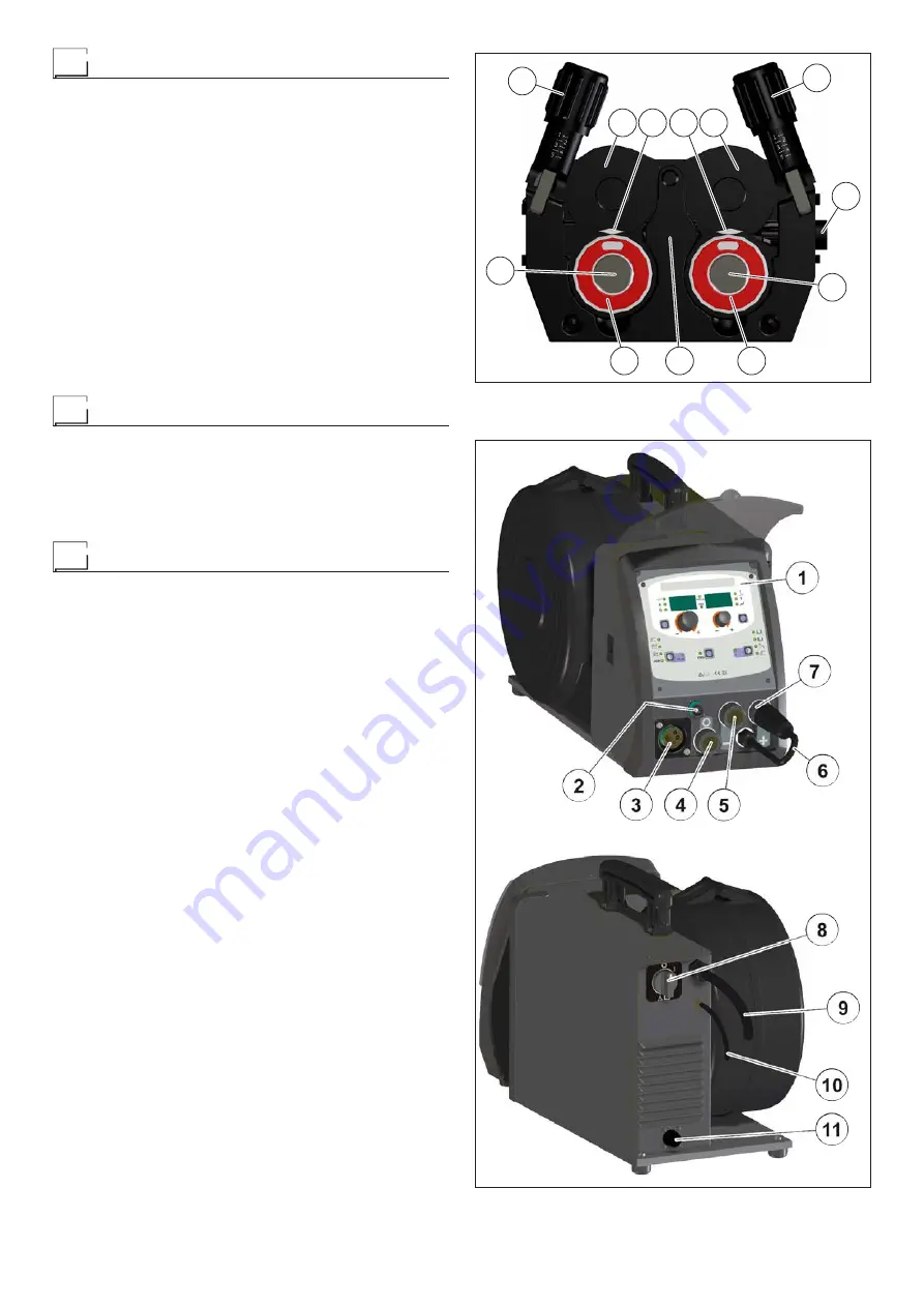
Thread the end of the wire into the back guide (Pos. 1, Fig. A)
on the drawing mechanism.
•
Lift up the idle rolls (Pos. 4, Fig. A) releasing the roll pres-
sure device (Pos. 2, Fig. A). Make sure that the drive rolls
(Pos. 7, Fig. A) have the diameter corresponding to the wire
being used stamped on the outside.
•
Insert the wire into the central wire guide and the wire guide
on the centralised connection (Pos. 5, Fig. A) by a few cen-
timetres. Lower the idle roller holder arms, making sure that
the wire slots into the hollow in the motor’s roller. If neces-
sary, adjust the pressure between the rollers by turning the
relevant screw (Pos. 2, Fig. A). The correct pressure is the
minimum that does not allow the rollers to skid on the wire.
Excessive pressure will case deformation of the wire and tan-
gling on the entrance of the sheath; insufficient pressure can
cause irregular welding.
Assembly of drive rollers
Unscrew the two screws (Pos. 6, Fig. A). Lift up the idle roll-
holder arm (Pos. 3, Fig. A) and proceed as follows:
•
Each roller shows the type of wire and diameter on the two
external sides.
•
Install the right rolls (Pos. 7, Fig. A) making sure the groove is
in the correct position for the diameter of the wire being used.
Control welding power source
Fig. B
Pos. 1
control panel.
Pos. 2
Up/Down connector.
Pos. 3
Centralized torch connection.
Pos. 4
Rapid coupling neutral position, used only for MMA
and TIG electrode welding.
Pos. 5
Fast coupling positive polarity.
Pos. 6
Cable to change polarity.
Pos. 7
Fast coupling negative polarity.
Pos. 8
Power supply switch. In the “O” position the welding
power source is off.
Pos. 9
Mains cable.
Pos. 10
Gas hose.
Pos. 11
Connector for connecting the cooling system.
7
7
6
5
2
3
4
4
3
2
1
6
FIG. A
FIG. B
Содержание DIX PI GO 2006.M
Страница 13: ...13 2101AC73...


