System Components
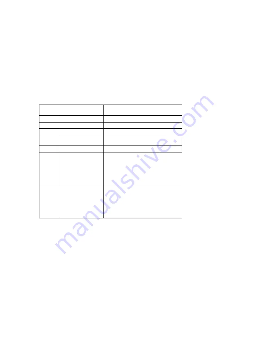
Table 2-2. Front Controls and Indicators
Figure
Legend
Control or Indicator
Function
1
Drive bays
Location of three upper 5¼-inch drive bays.
2
Hard drive
Location of hidden 3½-inch drive bay.
3
Floppy drive
Location of 3½-inch diskette drive.
4
Floppy eject button
Releases a 3½-inch diskette from the floppy
diskette drive.
5
Power On/Off button
Turns AC power on and off.
6
Halt/Reset button
When set to Halt, this button is operating
system-specific. See your operating system
documentation. When set to Reset (default),
this button resets the system and causes the
self test to run. See Appendix C, Technical
Specifications, for setting the Halt/Reset
jumper.
7
Indicators
Indicators from top to bottom are as follows:
•
Power indicator lights when the
system is on.
•
Hard disk drive indicator lights when a
hard disk drive is in use.
•
The lower indicator is not used.
2-5
Содержание Digital AlphaStation 400 Series
Страница 4: ......
Страница 30: ......
Страница 38: ......
Страница 53: ...Expanding Your System Figure 3 11 SCSI and FDC Cable Configuration 3 15...
Страница 56: ...Expanding Your System MLO 012675 Figure 3 13 Removing the Lower Drive Bay Assembly 3 18...
Страница 58: ......
Страница 90: ......
Страница 102: ......


