background image

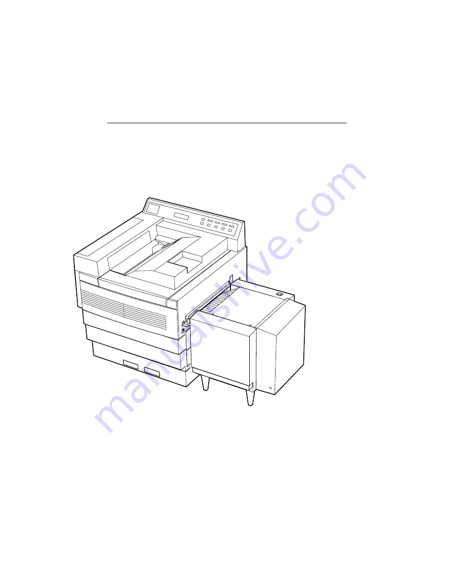
DEClaser 3200/3250

Service Guide

EK–LN08Z–SV–001

Digital Equipment Corporation
Maynard, Massachusetts

Содержание DEClaser 320

Страница 1: ...DEClaser 3200 3250 Service Guide EK LN08Z SV 001 Digital Equipment Corporation Maynard Massachusetts...

Страница 2: ...ver ReGIS VAX DOCUMENT and the DIGITAL Logo are trademarks of Digital Equipment Corporation BITSTREAM is a registered trademark of Bitstream Inc Centronics is a trademark of Centronics Data Corporatio...

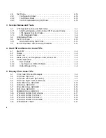
Страница 3: ...pment 1 14 2 Control Panel Operations and Menus 2 1 Control Panel Keys and Indicators 2 1 2 2 Operational Display Format 2 5 2 2 1 Operational Status Messages 2 6 2 3 About the Customer and Service Me...

Страница 4: ...FIP 4 2 4 2 Noises 4 3 4 3 Fuser Fan 4 5 4 4 Blank Silent and Inoperative Control Panel FIP 4 6 4 5 Erratic Operation 4 7 4 5 1 Bad Grounds 4 8 4 5 2 Line Power or LVPSA Problems 4 8 4 5 3 High Volta...

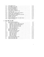
Страница 5: ...5 37 6 Paper Path Jam FIPs 6 1 Jams and Paper Misfeeding 6 2 6 2 0820 0824 CLEAR PAPER PATH 6 4 6 2 1 Registration Transport Diagram and Tests 6 6 6 2 2 0820 Paper Under the BYPASS Sensor 6 8 6 2 3 0...

Страница 6: ...lack Spots 7 16 7 13 Fusing Failure 7 17 7 14 Black Lines or Streaks 7 18 7 15 HVPSA FIP 7 19 7 16 Erase FIP 7 20 7 17 Developer Bias FIP 7 21 8 RSL and Parts Location 8 1 Recommended Spares List 8 1...

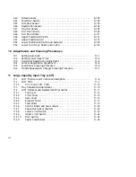
Страница 7: ...9 56 9 22 Upper Bracket 9 57 9 22 1 Fuser Fan 9 59 9 22 2 Control Panel 9 60 9 23 Laser Scanner Assembly 9 61 9 24 Top Door Scanner Interlock Sensor 9 64 9 25 Transfer Separation Charger 9 65 9 26 Era...

Страница 8: ...3 10 4 Vertical Registration Adjustment 10 4 10 5 Feed Roller Cleaning Procedure 10 5 10 6 Transfer Separation Charger Cleaning Procedure 10 7 11 Large Capacity Input Tray LCIT 11 1 LCIT Physical and...

Страница 9: ...r B 3 B 2 2 Envelope Specifications B 3 B 2 2 1 Special Considerations When Printing on Envelopes B 4 B 2 3 Transparency Specifications B 4 B 2 3 1 Special Considerations When Printing on Transparenci...

Страница 10: ...RAY SELECTION E 10 E 2 3 DUPLEX E 10 E 2 4 FONT NUMBER E 11 E 2 5 PAPER SIZE E 11 E 2 6 ORIENTATION E 12 E 2 7 FORM LENGTH E 12 E 2 8 SYMBOL SET E 13 E 3 PostScript Submenu E 14 E 3 1 DUPLEX E 16 E 3...

Страница 11: ...1 1948 Service Menu SETUP PATTERN 3 10 3 2 Error Log 3 11 3 3 Test Print Menu 3 12 3 4 Test Menu Patterns 3 14 4 1 Overall Troubleshooting Flow 4 1 4 2 Connectors 4 7 5 1 Overall Troubleshooting Flow...

Страница 12: ...12 Refeed Trailing Edge Jam 6 19 6 13 Registration or Shingle Jams 6 21 6 14 Registration Sensor and Clutch 6 23 6 15 Cassette Magnets 6 25 6 16 Gate Area Jams 6 28 6 17 Gate Linkage and Sensor Circu...

Страница 13: ...E 1 DEC PPL3 Submenu E 2 E 2 LJ2D Submenu E 9 E 3 PostScript Submenu E 15 Tables 1 1 Printer Components Front View 1 3 1 2 Printer Components Rear View 1 5 1 3 Printer Components Inside View 1 7 1 4 S...

Страница 14: ...cation 9 30 9 2 DC Control Board Harness 9 38 11 1 LCIT External View 11 3 11 2 Internal Rear Side View 11 5 11 3 Internal Front Side View 11 7 11 4 LCIT Error Code Lookup Table 11 10 A 1 Parallel Int...

Страница 15: ...this service guide Convention Description Note Notes provide additional information Caution Cautions emphasize information for preventing damage to the equipment or software Warning Warnings emphasize...

Страница 16: ...you verify the correct operation of the printer or isolate a malfunction The Start FIP will direct you to other specific FIPS described in Chapters 4 5 6 7 and 10 Chapter 5 Interprets the display pan...

Страница 17: ...about the features and values available on the three protocol submenus You select these menus from the PROTOCOL feature of the Set Up menu which is described in Section 2 4 The DEC PPL3 and LJ2D proto...

Страница 18: ......

Страница 19: ...omplies with 21 CFR Chapter 1 Subchapter J as a Class 1 laser product under the U S Department of Health and Human Services DHHS Radiation Performance Standard according to the Radiation Control for H...

Страница 20: ...on Figure 1 1 presents a view of the front and right side of the printer To find the names and function of the items pointed to see Table 1 1 Figure 1 1 Printer Components Front View MLO 006248 1 2 4...

Страница 21: ...2 for more information Manual feed tray and bypass slot The manual feed tray is removed when you install the optional feeder The bypass slot is used for manual or optional equipment paper feeding such...

Страница 22: ...presents a view of the rear and left side of the printer To find the names and function of the items pointed to see Table 1 2 Figure 1 2 Printer Components Rear View 9 8 1 5 6 7 MLO 006249 2 3 4 1 4...

Страница 23: ...be removed to install a future connectivity option Power cord receptacle This is where the power cord connects to the printer Serial interface connector Accepts the standard 6 pin MMJ connector and i...

Страница 24: ...Figure 1 3 shows components inside of the printer To find the names and function of the items pointed to see Table 1 3 Figure 1 3 Printer Components Inside View 2 3 4 5 6 MLO 006631 1 1 6 Physical an...

Страница 25: ...ient light for more than 10 minutes The electronic device encased in the print drum contains ID and status information See Table 3 1 for more information Developer cartridge or unit This user replacea...

Страница 26: ...eets From the following submenus you select the cassette and the failover characteristics To display a submenu first press Set Up then select the PROTOCOL feature See Section 2 4 and Section 2 4 1 for...

Страница 27: ...Cassette Feeders When printing duplex load forms and letterheads faceup bottom edge inserted first Figure 1 4 MAX Limit and Snubbers 26 5 MLO 006271 Paper Snubber Physical and Functional Description...

Страница 28: ...select from many standard sizes or enable the host system Refer to Section 2 4 for cassette adjust menu information Furthermore the customer can identify each adjustable cassette as an A or B cassette...

Страница 29: ......

Страница 30: ......

Страница 31: ...sette Paper Size sensing Magnets Size S1 S2 S3 Cassette not installed OFF OFF OFF Adjustable A ON OFF OFF A4 210 x 297 mm OFF ON OFF Legal 8 5 x 14 OFF ON ON Adjustable B ON OFF ON A51 ON ON OFF Lette...

Страница 32: ...ard mounts in a SIM socket J10 on the video control board It provides processing power for the PostScript interpreter Without a functional coprocessor the printer will fail to operate in PostScript mo...

Страница 33: ...ppendix E for more Set Up menu information Section 2 4 describes the Set Up menu features such as the protocol and communications parameters Section 2 5 describes the Defaults menu which you use to re...

Страница 34: ...liquid crystal display that shows status messages in conjunction with the other indicators Section 2 2 explains the display format See Table 5 1 for a brief interpretation of the error code and for a...

Страница 35: ...r If enabled the beeper will sound If an error message and code fails to appear on the display press 3 to display one See Table 5 1 for a brief interpretation of the error code and for a pointer to th...

Страница 36: ...Chapter 3 for additional information 3 The following functions are performed by this key In any menu this key enters or invokes settings test codes and commands When the Supply indicator is on this ke...

Страница 37: ...l operation of the DEClaser 3200 printer The display is divided into four sections for all modes of operation Figure 2 2 Printer Status Display Set Up Test Last Page Supplies Error Online Defaults Onl...

Страница 38: ...but will receive data until the buffer fills Press Online Pause to continue BUSY The printer is receiving processing or printing data Pressing Online Pause while the BUSY message is displayed causes t...

Страница 39: ...llowjobreset is true PRESS 3 TO ABORT2 Instructs the operator to press 3 to abort the current print job PostScript operator allowjobreset is false INITIALIZING PS2 Displayed when the PostScript protoc...

Страница 40: ...g Protocol Level 3 Programming Supplement 2 3 2 Set Up Memory Organization Figure 2 3 shows the organization and flow characteristics of Set Up memory within the DEClaser 3200 control panel Figure 2 3...

Страница 41: ...vances to the next level of operation in the menu o Decreases numeric values in LJ2D protocol 3 o Selects the current feature or value shown on the display 2 4 Set Up Menus The Set Up menus and submen...

Страница 42: ...NTROL 1200 2400 4800 9600 19200 38400 ONCE 3 TIMES CONTINUOUS DISABLED 7 BIT ODD 7 BIT EVEN 7 BIT MARK 7 BIT SPACE 7 BIT NONE 8 BIT ODD 8 BIT EVEN 8 BIT NONE XON XOFF 2 WAY XON XOFF 1 WAY DTR READY HI...

Страница 43: ...ns See Section E 1 for further information LJ2D This is the resident Hewlett Packard s PCL operating protocol See Section E 2 for further information POST2 Is the optional PostScript operating protoco...

Страница 44: ...5 in paper size 215 X 275 Selects 215 mm x 275 mm paper size 1 Factory default setting 2 4 3 ALARM Table 2 6 shows the values that are available from the ALARM feature See Figure 2 4 to find the posi...

Страница 45: ...d of the printer and host must match or communication errors will occur PARITY2 8 BIT NONE1 7 BIT ODD 7 BIT EVEN 7 BIT MARK 7 BIT SPACE 8 BIT ODD 8 EVEN Parity checking detects communication errors th...

Страница 46: ...layed in the selected language Service call messages are only displayed in English 1 Factory default setting 2 4 6 COMM ERROR Table 2 9 shows the values that are available from the COMM ERROR feature...

Страница 47: ...ry default settings from ROM into the operating memory for current use RECALL USER DFT1 Loads the settings saved by the user from NVRAM into the operating memory for current use SAVE DEFAULTS1 Saves t...

Страница 48: ...us Sheet Start CR mode Stop CR mode See Section 2 6 3 Control Representation CR Mode 2 6 1 Configuration Sheet Figure 2 5 is an example of a DEClaser 3200 Configuration sheet Section 2 6 describes the...

Страница 49: ...200 Printer Page Count 1268 Page Description Language Co processor Not Installed Available Memory 295892 bytes Saved Settings Current Setting LJ2D LETTER LETTER ONCE SERIAL NA NA NA BUSY HIGH ENGLISH...

Страница 50: ...Level 3 Programming Reference Manual 2 6 3 Control Representation CR Mode The Control Representation or Character Dump mode is used to print out raw unprocessed data or commands sent from the host com...

Страница 51: ...LTN1101VK00GG0001UZZZZ02F000 DBULTN1 DBULTN1101VK00GG00245ZZZZ02F000 DBULTN1 DBULTN1101VK00GG006DDZZZZ02F000 D000000 D000000101VK00GG0001QZZZZ02F000 D000000 D000000101VK00GG0001CZZZZ02F000 DBULTN1 DBU...

Страница 52: ......

Страница 53: ...is chapter These codes are only published in this service guide 3 1 1701 Special Function and Test Codes Table 3 1 and Table 3 2 list all of the codes that you can use to obtain status information tes...

Страница 54: ...and return to normal operation power the printer down and then up Running and Selecting a Function or Test Code Use the following procedure to enter and run a 1701 function or test code 1 To start th...

Страница 55: ...on does not work English or 2 nd language 0281 301 Set read contrast or the LCD display 00 0F 0281 401 Beeper control ON OFF 0282 01 0282 01 Horizontal Registration set menu See Section 10 3 for the a...

Страница 56: ...djustment If any value other then 03 is displayed reset the 03 factory default value 0282 80 Set scanner auto on time See Section 10 1 for the adjustment procedure 0282 90 Set fuser power saver time S...

Страница 57: ...rheating device test time is limited to 10 seconds Table 3 2 1701 Test Codes Test Code Display or Prompt Definition 0100 SENSING Top cover LVPSA interlock switch 0101 SENSING Feed door sensor 0102 SEN...

Страница 58: ...licks Lower feed solenoid 0803 Complete Runs the LCIT paper feed motor if the LCIT is connected and loaded with paper The INVALID message is displayed if the LCIT is not attached 0804 Clicks Refeed cl...

Страница 59: ...on at high speed 1101 COMPLETE The exit motor in forward direction at low speed 1102 COMPLETE The exit motor in reverse direction 1103 COMPLETE Offset motor test Use the following procedure 1 Select a...

Страница 60: ...Press Online Pause until the PAUSED message appears indicating that the printer is off line Test Setup 0 0 0 0 Simultaneously press and release Test and Set Up to display all zeros If you press one ke...

Страница 61: ...3 to print the error log described in Figure 3 2 or press to go to the next service menu entry The error log may print in portrait or landscape orientation depending on the orientation of the last pri...

Страница 62: ...f ever these mail s coverage Would yo your time to read survey has been de time and effort T test pattern a qu envelope are enclo We conduct many of ever these mail s coverage Would yo your time to re...

Страница 63: ...4 0921 0922 0923 0924 1001 Occurrence 1 2 PRINTER 1002 1003 1004 1005 1020 1021 1022 1023 1024 1025 1026 1111 1120 1401 1402 1403 1404 1405 1406 1407 1408 1410 1411 1412 1413 1414 1415 1416 1417 1418...

Страница 64: ...Test Print menu 5 Figure 3 3 shows the Test Print menu control panel display and keys Exiting the Test Print Menu To terminate and leave the Test Print menu power down the printer Figure 3 3 Test Pri...

Страница 65: ...start or stop the continuous feeding print job Press Test to step through the C W B test prints Figure 3 4 shows examples of the three test patterns Press Defaults to change to the following feed dev...

Страница 66: ...service a DEClaser 3200 printer If during the procedure the control panel hangs or an error message is displayed go to Section 4 1 1 Power down the printer 2 Remove any installed font cartridges 3 Pow...

Страница 67: ...ess until DEC PPL3 appears 8 Press 3 to select DEC PPL3 The asterisk 3 will appear next to DEC PPL3 Unless you save the defaults as shown in Section 2 5 the original protocol will return at power up 9...

Страница 68: ......

Страница 69: ...FIP in Chapters 4 5 6 or 7 If you follow a sequence of steps to the resolution of one problem return to the Start FIP Figure 4 1 Overall Troubleshooting Flow Section 4 1 Troubleshooting Start FIP None...

Страница 70: ...s blank scrambled or hung up and the indicators are inoperative or not correct go to Section 4 4 Blank Silent and Inoperative Control Panel FIP If the printer makes questionable noises go to Section 4...

Страница 71: ...anical parts are lubricated for the life of the printer Troubleshooting Use the following steps to isolate and find the source of the noise 1 Noises in standby Inspect the following if you fail to hea...

Страница 72: ...upper and lower registration and upper and lower feed rollers 4 Noises during printing Print a test sheet as shown in Chapter 3 Do the following to find the source of noise heard while the printer is...

Страница 73: ...he fan by entering the 1701 test code 1010 When you press 3 the fan will accelerate Do the following if the fan fails to turn turns slowly or fails to accelerate 1 If the fan runs but fails to acceler...

Страница 74: ...the TEST LED on the rear of the printer The fan is powered by the 24 Vdc supply through the 2 pin P52 connector on the LVPSA The TEST led is powered by the 5 Vdc power supply If the fan is exhausting...

Страница 75: ...DC control board Control panel 5 Figure A 2 shows the location of each connector in upper portion of the DEClaser 3200 printer Inspect each connector if the printer is intermittently failing 4 5 Erra...

Страница 76: ...the LVPSA to see if the problem goes away Look for a short or open circuit in the distribution network or in a discreet device See Section A 5 for diagrams of the low voltage power distribution networ...

Страница 77: ...the 1701 test code 0400 07 as shown in Section 3 1 1 This runs the main motor and all HVPSA outputs d Look and listen for arcing in all the high voltage cables and connectors It might be easier to se...

Страница 78: ......

Страница 79: ...ng flow If you follow a sequence of steps to fix one problem return to Section 4 1 Start FIP Figure 5 1 Overall Troubleshooting Flow MLO 007644 Arrive at Site Appendix C TCC Procedure Leave the Site C...

Страница 80: ...rol panel display Table 5 1 lists all the error messages and codes For troubleshooting information turn to the section listed under the full description column Figure 5 2 Error Message and Code Displa...

Страница 81: ...er out sensor detects empty cassette 07021 Section 5 12 Lower paper out sensor detects empty cassette 07031 Section 5 13 LCIT paper out sensor detects empty LCIT 07051 Section 5 14 Upper cassette is m...

Страница 82: ...it Fuser temperature too low Fuser temperature too high Fuser heater has been on too long 10201 1021 1022 1023 1024 Section 6 6 Fuser jam when feeding from bypass slot Fuser jam when feeding from uppe...

Страница 83: ...4 Section 5 24 Font cartridge error 15024 1503 Section 5 25 Memory board SIM error 15084 Section 5 26 Coprocessor error 15094 Section 5 27 NVRAM error 1511 1519 Error codes for future options 15202 Se...

Страница 84: ...the interlock switch Go to one of the following steps The top cover interlock circuit works correctly when the switch is manually depressed but has problems when the cover is opened or closed Inspect...

Страница 85: ...witch is actuated by the permanent magnet that is mounted on the exit door Troubleshooting Test the operation of the exit door switch and circuit Enter 0102 to invoke the 1701 test as shown in Section...

Страница 86: ...closes 2 Inspect the 19 pin plugs that connect P56 of the driver board to P57 of the DC control board The door open signal can be measured on pin 14 of that cable 3 Swap the sensor 4 Swap the driver b...

Страница 87: ...he switch and circuit open and close the door or pass a magnet close to the sensor The contacts close when the magnet is next to the switch Go to one of the following steps If a magnet can operate the...

Страница 88: ...rror Troubleshooting With the exception of the page count ROM you should not replace individual components of the DC control board Do the following when one of these codes is displayed 1 If 0301 is di...

Страница 89: ...D turns off Figure 5 6 Rear Error LED 1 MLO 006642 1 Watch the LED and turn on the printer power 2 If LED never comes on do the following a Inspect the 2 wire cables that connect the 4 pin P J7 connec...

Страница 90: ...ol board Swap the video control board 5 Do the following if the action of the LED is ambiguous or fails to resolve the problem a Inspect the 26 pin cable harness that connects P37 on the DC control bo...

Страница 91: ...DC control board See Figure 5 7 for the location of the devices 0312 is displayed if a NVRAM error is found 0313 is displayed if a EPROM error is found Troubleshooting Perform the following procedure...

Страница 92: ...operly as shown in Section 5 2 Perform the following steps 1 Inspect the 7 wire cable that connects from P35 on the DC control board to the motor control board 2 Use the following procedure to inspect...

Страница 93: ...LL SERVICE Description A 0600 or 0601 error code indicates that the Start of scan SOS signal is late 600 or was never 610 received by the DC control board The SOS signal is generated when the laser be...

Страница 94: ...ttern prints with no image defects the test is successful Test the scanner motor by entering the 1701 code 0610 to invoke the scanner motor test as shown in Section 3 1 3 When entered the motor should...

Страница 95: ...pass sensor Test both sensors by entering the 1701 test codes 0710 for the bypass and 0810 for the registration Perform the following steps to fix a problem Figure 5 10 700 Error P J 71 Developer Inte...

Страница 96: ...y 4 Pin MLO 006646 16 Pin P J 33 Upper Paper Out Troubleshooting Test the upper paper out sensor by entering the 1701 test code 0721 as shown in Section 3 1 3 When the test is sensing open the feeding...

Страница 97: ...stack into the sensor arm The sensor connects through the lower size sensing sensor assembly to 4 pin P J43 on the DC control board as shown on Figure 5 12 Figure 5 12 702 Error Lower Size Sensing Ass...

Страница 98: ...malfunctions can cause this error Troubleshooting Before performing the following FIP make sure the printer is in good working order Select a cassette and feed test prints from it 1 Make sure the LCIT...

Страница 99: ...ze sensing switches by entering the 1701 test code 0711 The control panel lights up when a cassette is inserted If the cassette fails to activate the switches pass a magnet over the sensor pack Perfor...

Страница 100: ...cassette Figure 5 13 shows the wiring diagram See Section 1 3 3 for more information about the cassette size sensing circuits Troubleshooting Test the size sensing switches by entering the 1701 test c...

Страница 101: ...igure 5 14 shows the wiring diagram If the voltage is greater than 15 7 the printer will configure itself for an LCIT Troubleshooting Before performing the following FIP make sure the printer is in go...

Страница 102: ...ges The print drum is also referred to as cartridge A An electronic memory is molded into the print drum cartridge The DC control board periodically writes and reads the print drum memory The memory d...

Страница 103: ...ard 3 Inspect the connection of the 20 pin plug P J36 that connects to the DC control board 4 Swap the following components a Print drum cartridge A b DC control board c Erase board 5 18 0911 0914 CAR...

Страница 104: ...ation replace that FRU 2 Inspect the connection of the 10 pin plug P J34 that connects to the DC control board 3 Swap the following components a Developer cartridge C b DC control board c Developer in...

Страница 105: ...emory test fails perform the following steps 1 Remove the developer cartridge and inspect the condition of the spring contacts that connect the developer to the interconnect board Wipe any dirt from t...

Страница 106: ...uit is open 1003 Fuser is too hot 1004 Fuser is always on Figure 5 15 Fuser Circuit and Connectors Fusing Unit Over Temp P J 51 Driver Board P J 10 Interlock Switch Power Switch Fuser Triac Power Cord...

Страница 107: ...he LVPSA 2 pin plug that connects the thermistor to the wire harness at the front of the printer P56 that connects the wire harness to the driver board P J47 that connects the wire harness to the DC c...

Страница 108: ...owing procedure 1 Inspect the two clips that hold the sensor linkage to the frame of the exit assembly Make sure the linkage is properly attached and when raised actuates the tray full sensor Figure 5...

Страница 109: ......

Страница 110: ...Test the operation of the offset sensor by entering the 1701 test code 0815 as shown in Section 3 1 3 The control panel lights and beeps when you move the offset arm to its home position The test fail...

Страница 111: ...47 P J 47 P J 56 Driver Board P J 56 P J 55 DC Control Board 0815 5 VDC 18 2 1 2 1 P J 55 Offset B Offset Motor 2 1 Offset A 5 RET 10 1103 9 18 10 9 Offset Home L 5VDC 3 4 Offset Home Switch Normally...

Страница 112: ...he attached host system and printer are the same 3 Inspect or swap the cable that connects the printer to the host system or DCE 4 Swap the video control board 5 24 1500 REPLACE CARTRIDGE 1 2 Descript...

Страница 113: ...igure 5 18 shows the location of the socket on the video control board Table 5 2 Memory SIM and Socket Allocation 1502 1503 Display Socket Number REPLACE MEM BD 1 J15 REPLACE MEM BD 2 J14 REPLACE MEM...

Страница 114: ...roubleshooting on Figure 5 19 shows the location of the coprocessor connector P J10 on the video control board Perform the following steps to fix the fault 1 Inspect the installation of the coprocesso...

Страница 115: ...eo control board 5 29 1521 1523 REPLACE ADD PDL BD MEMORY Description This error code is displayed when an error is detected in the PDL option SIM that is installed in the socket U16 on the video cont...

Страница 116: ......

Страница 117: ...low a sequence of steps to fix one problem return to Section 4 1 Start FIP Figure 6 1 Overall Troubleshooting Flow MLO 007645 Arrive at Site Appendix C TCC Procedure Leave the Site Section 4 1 Trouble...

Страница 118: ...R PAPER PATH message and a specific error code is displayed Figure 6 2 uses numbered CALLOUTS to label the five paper path jam areas Table 6 1 briefly describes each jam type error code and directs yo...

Страница 119: ...x refeed preregistration jam 0826 Section 6 3 Duplex refeed leading edge jam 0827 Section 6 4 Duplex refeed trailing edge jam 0830 0831 0832 0833 0834 Section 6 5 Shingle type jam in the following are...

Страница 120: ...e or any of the electronic or mechanical support devices The following table and Figure 6 3 identify and locate the paper path components that cause 0820 through 0824 error codes Registration sensor a...

Страница 121: ...on transport which you can use to isolate a malfunction beyond the FRU level 1 Make sure the cassettes or LCIT is properly loaded with the correct size and type of paper 2 Test and repair the paper pa...

Страница 122: ...of the following FIPs if the sheet never reaches the upper turn roller or never leaves the selected feed source Section 6 2 2 0820 Paper Under the BYPASS Sensor Section 6 2 3 0821 Upper Cassette Feed...

Страница 123: ...r gear damage and listen for thumps or grinding noises Figure 6 4 Registration Sensor and Upper Turn Clutch DC Control Board 5 VDC 7 6 5 0810 7 P J 38 Paper Reg H 5 VDC Registration Sensor 5 RET 5 VDC...

Страница 124: ...oting Test the bypass sensor by entering the 1701 Test codes 0710 Figure 6 5 shows the wiring diagram Perform the following steps to fix a problem 1 Inspect the following for misconnection or mechanic...

Страница 125: ...alled paper holding down the registration sensor or a bad sensor If this error is constantly displayed or appears intermittently at powerup or without feeding go to Section 6 2 The result of a misfeed...

Страница 126: ...s for any damage or missing teeth 6 Clean the paper feed rollers as shown in Section 10 5 7 Swap the upper feed roller clutch Figure 6 6 Upper Feed Solenoid Diagram DC Control Board 1 2 0801 P J 39 SO...

Страница 127: ...olenoid The spacer was added to early printers to correct a slight timing problem On later models the height of the plastic boss that the solenoid mounts on was altered to eliminate the spacer Figure...

Страница 128: ...to energize the lower turn roller clutch for 10 seconds Test the clutch by manually rotating the lower turn roller It must turn freely when the clutch is deactivated and lock up when the clutch is en...

Страница 129: ...to check the operation of the LCIT If this test fails go to Chapter 11 to diagnose the LCIT 3 Remove inspect and fan the paper in the LCIT Look for damage sticking or wrinkling and curling 4 Ensure th...

Страница 130: ...aper feed motor DC control board Figure 6 9 LCIT Paper Feed Connectors P J 41 P J 90 P J 9 BLU ORN BLK RED GRN YEL BRN GRY 24 VDC 5 VDC No Paper HCF Sense Feed Paper Size Sense BLU GRN BLK RED WHT YEL...

Страница 131: ...can assume that the refeed rollers and sensor worked all right if a 1025 error code was not displayed Troubleshooting This error can occur if feeding shorter paper and may not occur feeding longer pap...

Страница 132: ...Refeed Leading Edge Jam 2 3 1 MLO 006662 Troubleshooting If the duplex refeed sheet fails to arrive underneath the feed roller the top sheet in the upper cassette may feed in its place Before troubles...

Страница 133: ...the 20 pin plug that connects P J56 on the driver board to P J47 on the DC control board c Swap the following Refeed sensor Driver board DC control board 3 Test the reverse operation of the exit rolle...

Страница 134: ...P J 53 12 19 3 3 P J 56 P J 52 Clutch ON L 24 VDC 24 VDC 2 1 Refeed Sensor 7 2 3 1 Refeed Clutch P J 58 P J 84 P J 53 MLO 006658 2 1 6 4 0827 CLEAR PAPER PATH Description This error is displayed when...

Страница 135: ...re 1 Remove and inspect the upper cassette for the following Is the clear plastic cassette top missing broken or contaminated with adhesives Are there any cuts or burs on the top of the cassette Is th...

Страница 136: ...iption Error codes 0830 through 0834 indicate a registration or shingle type jam When the registration sensor fails to detect the trailing edge of the sheet the error code for that feed source is disp...

Страница 137: ...t and repair the paper path by first feeding sheets from the upper cassette then feeding from the lower cassette When you are certain that the cassettes function correctly feed from the LCIT 3 Perform...

Страница 138: ...used to troubleshoot to components beyond the FRU level Enter 0400 01 to run the drive gears Look for jerky motion caused by missing teeth or gear damage and listen for thumps or grinding noises Ente...

Страница 139: ...ration Sensor and Clutch DC Control Board 5 VDC 7 6 5 0810 7 P J 38 Paper Reg H 5 VDC Registration Sensor 5 RET 5 VDC LED 7 2 3 1 P J 38 MLO 006654 3 4 0851 P J 38 Clutch ON L 24 VDC Upper Turn Roll C...

Страница 140: ...ng operator problems Inserts the sheet too late Fails to fully insert the sheet The registration rollers fail to grab the leading edge Operator is inserting the wrong size paper 2 Inspect the manual f...

Страница 141: ...the cassette magnets See Table 6 2 and Figure 6 15 Table 6 2 Cassette Size sensing Cassette Paper Size sensing Magnets Size S1 S2 S3 Cassette not installed 0 0 0 A4 0 1 0 A5 1 1 0 8 5 in x 14 in 0 1...

Страница 142: ...e the roller turns freely and the pressure springs and door are installed properly 8 Test the lower feed solenoid by entering the 1701 test code 0802 When entered the solenoid energizes 5 times You ca...

Страница 143: ...iption This error code is displayed when the registration sensor fails to detect the trailing edge of a sheet that is fed from the duplex refeed The duplex refeed paper path consists of the top of the...

Страница 144: ...er cassette feeding 1022 Lower cassette feeding 1023 LCIT feeding 1024 Duplex refeed feeding Figure 6 16 Gate Area Jams MLO 006665 1 2 Troubleshooting Use the Test Print menu See Section 3 3 to feed a...

Страница 145: ...e of the developer unit Make sure it turns freely and the pressure springs function 6 Test the gate sensor circuit by entering the 1701 test code 0811 After entering manually actuate the gate linkage...

Страница 146: ......

Страница 147: ...6 22 shows the wiring diagram Do the following if the test fails Inspect the 20 pin plug that connects P J56 on the driver board to P J47 on the DC control board Inspect the 6 pin plug connecting the...

Страница 148: ......

Страница 149: ...the following procedure 1 Open the exit door and inspect the paper path for damage or obstructions 2 Make sure the top part of the postfuser transport closes and locks When the exit door closes it pus...

Страница 150: ...ol board Swap the driver board Figure 6 20 Exit Sensor DC Control Board 5 VDC 1 2 0812 7 P J 47 5 RET P J 56 P J 47 Driver Board 2 1 12 P J 56 12 1 3 1 P J 58 Paper Sensed H 5 VDC 5 VDC 2 Exit Sensor...

Страница 151: ...diagram Perform the following procedure 1 Inspect the exit pinch roller pressure springs Make sure the springs are installed and are applying firm even pressure 2 If the surface of either exit roller...

Страница 152: ...sensor assembly Figure 6 22 Exit Motor P J 47 P J 47 P J 56 Driver Board P J 56 P J 54 DC Control Board 1102 6 6 P J 54 24 VDC Exit Motor 2 1 24 VDC 1100 3 3 3 4 4 5 24 VDC 7 7 8 8 24 VDC Return DMa D...

Страница 153: ...to fix one problem return to Section 4 1 Start FIP Figure 7 1 Overall Troubleshooting Flow MLO 007646 Arrive at Site Appendix C TCC Procedure Leave the Site Section 4 1 Troubleshooting Start FIP Chapt...

Страница 154: ...on Section 7 2 Background Staining Section 7 3 Black Prints Section 7 4 Blank Prints Section 7 5 Damaged Prints Section 7 6 Deletions Blank or White Spots Section 7 6 1 Vertical Deletions or White Ban...

Страница 155: ...veral test patterns at each extreme Inspect the gray or background areas of both prints No staining should occur A slight density change will be noticeable If you see no change in density go to Sectio...

Страница 156: ...ever these mail s coverage Would yo your time to read survey has been de time and effort T test pattern a qu envelope are enclo We conduct many of ever these mail s coverage Would yo your time to read...

Страница 157: ...f the pattern is all black replace the DC control board If the print is not all black do the following Swap the video control board Replace the 26 pin cable harness that connects P37 on the DC control...

Страница 158: ...that connects the scanning assembly to the wire harness to P36 on the DC control board Tighten the screw that connects the two ground wire ring connectors to the metal shield of the scanning assembly...

Страница 159: ...aper guides rollers transport assemblies Look for warped covers adhesives contamination wadded shreds of paper and so on Make sure the transfer separation charger is fully seated and locks into place...

Страница 160: ...rform the classification procedure in Section 7 6 Troubleshooting Suspect bad paper consumables paper path damage or light path obstructions Perform the following procedure 1 The toner might be damp a...

Страница 161: ...ite Bands Description One or more bands of white running horizontally across the sheet Perform the classification procedure as shown in Section 7 6 Troubleshooting Suspect rollers or any horizontal co...

Страница 162: ...shown in Section 3 3 and the 1948 Setup pattern as shown in Section 3 3 Also ask the customer to print samples of the offending defect Analyze the printed samples and go to one of the following 1 If t...

Страница 163: ...Inspect the test patterns All of the number 1 lines must be visible and unbroken Perform the following procedure to fix any defects 1 The paper might be damp Try some dry paper from the center of a fr...

Страница 164: ...the image is not centered on the test sheet perform the following procedure The paper might be compressed Remove and fan the paper The cassette and the metal corner snubbers Make sure the paper is co...

Страница 165: ...7 9 Misregistration Figure 7 3 Misregistration Grid Pattern 1 2 Lead Edge MLO 006673 Image Defects FIPs 7 13...

Страница 166: ...lace 3 Make sure all transports are correctly seated and aligned 4 If the skewing only occurs when feeding from the LCIT check the tray parallelism as shown in Section 11 3 5 Inspect the following pin...

Страница 167: ...7 10 Skewed Image 8 Make sure the exit and feed doors are undamaged and mounted correctly Figure 7 4 Skew Measurement 1 2 Lead Edge MLO 006674 Image Defects FIPs 7 15...

Страница 168: ...rtridge 6 If the defect occurs at intervals of approximately 3 75 in 95mm replace the fusing unit 7 Go to Section 7 16 and verify the operation of the erase LEDs 7 12 Black Spots Description Random or...

Страница 169: ...venly around the circumference of the roller 6 Swap the developer unit 7 13 Fusing Failure Description Fusing failure is indicated when you can brush or rub the toner off the sheet Troubleshooting Pri...

Страница 170: ...print cartridge Make sure the scanner window is not contaminated or blocked Make sure the scanner assembly is correctly mounted Swap the scanner assembly b Remove the developer unit and inspect the d...

Страница 171: ...ration has any physical damage 2 Inspect the following high voltage contacts The transfer separation wires and connector block The primary high voltage connector see Section 9 17 1 that connects the p...

Страница 172: ...ng FIP if one or more of the erase LEDs fail to light or if directed here from some other FIP 1 Remove the following parts a Print drum as shown in Section 9 11 b Top door cover as shown in Section 9...

Страница 173: ...hown in Section 9 12 2 Inspect and clean the following Replace any part that is bent pitted or otherwise damaged Spring contacts at the front and rear end of the developer roller shaft Developer bias...

Страница 174: ...7 17 Developer Bias FIP P J81 connector that connects the erase board to P J36 of the DC control board Figure 7 7 Developer Bias Connector 1 MLO 006679 7 22 Image Defects FIPs...

Страница 175: ...he DEClaser 3200 Illustrated Parts Breakdown for the part number or order information Table 8 1 DEClaser 3200 Recommended Spares List RSL Part Number R R Procedure Part Description 22 01341 01 NA Misc...

Страница 176: ...Top door scanner interlock sensor 29 29257 01 Section 9 25 Transfer separation charger 29 29256 01 Section 9 26 Erase board 29 29236 01 Section 9 27 Registration transport assembly 29 29306 01 Sectio...

Страница 177: ...Refeed sensor 29 29273 01 Section 9 44 Feed door sensor interlock switch 29 29264 01 Section 9 45 Exit door sensor interlock switch 29 29265 01 Section 9 46 Registration sensor 29 29262 01 Section 9...

Страница 178: ...ommended Spares List RSL Part Number R R Procedure Part Description 29 29706 01 Section 11 4 4 Elevator motor 29 29707 01 Section 11 4 5 Feed motor 29 29708 01 Section 11 4 6 Control board 29 29712 01...

Страница 179: ...Use Figure 8 1 Figure 8 2 and Figure 8 3 to identify the location of a part by the name that is listed in the accompanying table Figure 8 1 Covers Doors and External Parts 1 2 3 4 5 7 8 9 10 11 12 6 M...

Страница 180: ...ver Section 9 3 Right side cover Section 9 6 The cover is behind the manual feed guide Feed door Section 9 7 Lower front Cover Section 9 5 Video cooling fan Section 9 20 Figure 8 1 Right Photoreceptor...

Страница 181: ...8 2 Parts Locator Figure 8 2 Parts Locator 1 3 2 1 10 9 8 7 6 5 MLO 006682 4 4 1 2 3 MLO 007471 8 8 RSL and Parts Location...

Страница 182: ...Section 9 18 Part of drive board Video control board See Lower Figure 8 2 for more detail Main motor Section 9 36 LVPSA Section 9 16 DC control board Section 9 15 HVPSA Section 9 17 Developer intercon...

Страница 183: ...8 2 Parts Locator Figure 8 3 Parts Locator 2 2 1 11 10 9 8 7 6 5 4 3 MLO 006684 2 1 12 11 10 9 8 7 6 5 4 3 MLO 006683 8 10 RSL and Parts Location...

Страница 184: ...7 Upper cassette empty sensor Section 9 37 Lower cassette empty sensor Section 9 39 Figure 8 3 Lower Erase board Section 9 26 Offset motor assembly Section 9 35 Exit motor Section 9 34 Rear electronic...

Страница 185: ......

Страница 186: ......

Страница 187: ......

Страница 188: ......

Страница 189: ......

Страница 190: ......

Страница 191: ......

Страница 192: ......

Страница 193: ......

Страница 194: ......

Страница 195: ......

Страница 196: ......

Страница 197: ......

Страница 198: ......

Страница 199: ......

Страница 200: ......

Страница 201: ......

Страница 202: ......

Страница 203: ......

Страница 204: ......

Страница 205: ......

Страница 206: ......

Страница 207: ......

Страница 208: ......

Страница 209: ......

Страница 210: ......

Страница 211: ......

Страница 212: ......

Страница 213: ......

Страница 214: ......

Страница 215: ......

Страница 216: ......

Страница 217: ......

Страница 218: ......

Страница 219: ......

Страница 220: ......

Страница 221: ......

Страница 222: ......

Страница 223: ......

Страница 224: ......

Страница 225: ......

Страница 226: ......

Страница 227: ......

Страница 228: ......

Страница 229: ......

Страница 230: ......

Страница 231: ......

Страница 232: ......

Страница 233: ......

Страница 234: ......

Страница 235: ......

Страница 236: ......

Страница 237: ......

Страница 238: ......

Страница 239: ......

Страница 240: ......

Страница 241: ......

Страница 242: ......

Страница 243: ......

Страница 244: ......

Страница 245: ......

Страница 246: ......

Страница 247: ......

Страница 248: ......

Страница 249: ......

Страница 250: ......

Страница 251: ......

Страница 252: ......

Страница 253: ......

Страница 254: ......

Страница 255: ......

Страница 256: ......

Страница 257: ......

Страница 258: ......

Страница 259: ......

Страница 260: ......

Страница 261: ......

Страница 262: ......

Страница 263: ......

Страница 264: ......

Страница 265: ......

Страница 266: ......

Страница 267: ......

Страница 268: ......

Страница 269: ......

Страница 270: ......

Страница 271: ......

Страница 272: ......

Страница 273: ......

Страница 274: ......

Страница 275: ......

Страница 276: ......

Страница 277: ......

Страница 278: ......

Страница 279: ......

Страница 280: ......

Страница 281: ......

Страница 282: ......

Страница 283: ......

Страница 284: ......

Страница 285: ......

Страница 286: ......

Страница 287: ......

Страница 288: ......

Страница 289: ......

Страница 290: ......

Страница 291: ......

Страница 292: ......

Страница 293: ......

Страница 294: ......

Страница 295: ......

Страница 296: ......

Страница 297: ......

Страница 298: ......

Страница 299: ......

Страница 300: ......

Страница 301: ......

Страница 302: ......

Страница 303: ......

Страница 304: ......

Страница 305: ......

Страница 306: ......

Страница 307: ......

Страница 308: ......

Страница 309: ...e menu mode keys to set the 0282 80 code 5 Press 3 to enter the code The current setting or default is displayed The following example demonstrates Auto Scan menu 39 570 sec A dollar sign acts as a pr...

Страница 310: ...4 Press the menu mode keys to set the 0282 90 code 5 Press 3 to enter the code The current setting or default is displayed The following example demonstrates the power saver format 57 2730 A dollar s...

Страница 311: ...Registration set menu format 05 0 5mm A dollar sign acts as a prompt 05 This is the two digit hexadecimal set code The higher order digit 0 is always zero and it cannot be altered The lower order dig...

Страница 312: ...ates the Vertical Registration set menu format 0A 0 9mm A dollar sign acts as a prompt 0A The two digit hexadecimal set code The higher order digit 0 is always zero and it cannot be altered The lower...

Страница 313: ...he part numbers If the special tool is not available and the rollers need cleaning you must disassemble the printer to access the feed roller and clean it with an alcohol soaked towelette or replace t...

Страница 314: ...o packages and remove the alcohol towelettes 4 Wring the alcohol out of both towelettes onto both fur pads 10 Insert the cassette and cleaning tool Into the slot that was selected in step 6 above 11 P...

Страница 315: ...ansfer separation charger 1 Remove the transfer separation charger as shown in Section 9 25 2 Close the top cover to protect the photoreceptor drum 3 Gently clean the charge wire with a cotton swab un...

Страница 316: ...10 6 Transfer Separation Charger Cleaning Procedure Figure 10 1 Cleaning the Transfer Separation Charger MLO 006779 10 8 Adjustments and Cleaning Procedures...

Страница 317: ......

Страница 318: ......

Страница 319: ......

Страница 320: ......

Страница 321: ......

Страница 322: ......

Страница 323: ......

Страница 324: ......

Страница 325: ...EL 2 1 3 4 5 6 7 2 1 3 4 5 6 7 2 1 3 5 6 4 8 8 MLO 007437 0707 P J 41 P J 90 P J 9 BLU ORN BLK RED GRN YEL BRN GRY 24 VDC 5 VDC No Paper HCF Sense Feed Paper Size Sense BLU GRN BLK RED WHT YEL 2 1 3 4...

Страница 326: ......

Страница 327: ......

Страница 328: ......

Страница 329: ......

Страница 330: ......

Страница 331: ......

Страница 332: ......

Страница 333: ......

Страница 334: ......

Страница 335: ......

Страница 336: ......

Страница 337: ......

Страница 338: ......

Страница 339: ......

Страница 340: ......

Страница 341: ......

Страница 342: ......

Страница 343: ......

Страница 344: ......

Страница 345: ...lect a port through the COM INTERFACE feature of the Set Up menu as shown in Figure 2 4 A 1 1 Parallel Port The parallel port uses a Centronics interface protocol and a 36 pin connector Figure A 1 sho...

Страница 346: ...ignal Description 1 To printer STROBE L STROBE pulse low to read data A strobe low signal will raise BUSY line to high 2 To printer DATA BIT 11 3 To printer DATA BIT 21 4 To printer DATA BIT 31 5 To p...

Страница 347: ...printer SLCT H A high signal indicates the printer is in the select state A low signal occurs when printer is de selected or if an error condition exists 14 From printer Ground 15 From printer Stunt...

Страница 348: ...A 2 Serial Interface DEConnect Pin Direction Name RS 423 Function EIA 232 Equivalent 1 From printer TR TERMINAL READY CD 2 From printer SD SEND DATA BA 3 From printer SEND COMMON 4 To printer RECEIVE...

Страница 349: ...0 Series CPU DEC423 Ports BC16E1 H8571 E1 25 Pin Socket Devices Rainbow Digital Modems H8571 D BC16E1 H8571 E1 9 Pin Socket Devices IBM PC AT Type DECstation 210 212 DECstation 316 320 IBM PC AT H8571...

Страница 350: ...g Table A 4 Accessories and Supplies Part Number Description LN08X CA CG Times proportional font cartrigde LN08X CB CG Triumvirate proportional font cartridge LN08X CC ITC Souvenir and Script font car...

Страница 351: ...x LN01X AC Legal size paper 8 in x 14 in 5 000 sheets per box LN03X AJ Letter size transparencies 8 in x 11 in 50 sheets per box LN03X AK A4 size transparencies 297 mm x 210 mm 50 sheets per box H9850...

Страница 352: ...LVPSA P J 60 P J 73 P J 66 P J 65 P J 34 P J 74 P J 71 P J 73 P J 76 P J 47 P J 31 P J 40 P J 38 P J 35 P J 32 P J 41 P J 45 P J 48 P J 39 P J 33 P J 43 P J 37 P J 34 P J 36 P J 30 P J 52 P J 18 P J...

Страница 353: ...arness problems Figure A 3 15 Vdc Distribution Figure A 4 Overall Distribution Figure A 5 5 Vdc Distribution Figure A 6 24 Vdc Distribution Figure A 3 15 Vdc Distribution LVPSA P J 14 1 15 VDC P J 31...

Страница 354: ...15 VDC 5 VDC 8 24 VDC 9 24 VDC 6 7 1 P J 31 DC Control Board 5 4 7 6 12 10 TP2 TP1 TP3 P J 7 P J 18 2 5 VDC 2 1 3 2 5 VDC 1 P J 19 Video Cooling Fan Video Control Board 3 24 VDC 1 1 2 MLO 006686 4 LCI...

Страница 355: ...3 P J 81 P J 60 GRY P J 80 P J 81 Lower Paper Size Sensor Lower Tray Empty Sensor LCIT Option Developer Unit Developer Board Bypass Sensor Offset Home Switch Exit Cover Sensor Jam Cover Sensor Driver...

Страница 356: ...90 P J 36 GRY 3 24 VDC 9 5 4 2 17 17 Rear Fan RED P J 66 1 Lower Feed Solenoid 20 Scanner Assembly 7 P J 60 3 P J 47 Developer Interconnect S6 P J 34 Offset Motor Exit Motor Refeed Clutch Driver Board...

Страница 357: ...e cassette to its proper capacity rather than adding small amounts at a time When you unwrap a new package of paper discard the top and bottom sheets as they tend to absorb more humidity from the surr...

Страница 358: ...ons of transparencies and the glues used on envelopes and labels The inks and pigments used on chemically treated or coated paper such as preprinted forms or colored paper must also be able to withsta...

Страница 359: ...to the paper you must observe some special requirements with certain types of papers Do not use preprinted papers that do not meet the specifications for heat tolerance The ink from some preprinted p...

Страница 360: ...wing requirements when printing on envelopes Feed envelopes from the manual feed tray one at a time Print envelopes only on the front side Since you need to print addresses in a particular area on env...

Страница 361: ...eet and adhesive used for the labels must be able to meet the heat tolerance specification of 150 C 302 F for at least 0 1 second Caution Exposed adhesive on labels can cause damage to the printer To...

Страница 362: ...n 300 dpi Printing Speed Simplex 13 pages minute maximum using A4 or Letter size paper Duplex 11 pages minute maximum using A4 or letter size paper Warm Up Time Less than one minute at 20 C 68 F Paper...

Страница 363: ...pproximately 38 kg 85 lb Dimensions Width 670 mm 26 4 in Depth 536 mm 21 1 in Height 496 mm 19 5 in Built in RAM 0 5 MB expandable to 10 5 MB with optional SIMs Font Cartridges Capacity for two option...

Страница 364: ...sets For each DEC PPL3 font the following character sets reside in the printer ASCII DEC Supplemental ISO Latin 1 Supplemental DEC Technical DEC Special Graphics VT100 Line Drawing DEC 7 Bit Hebrew D...

Страница 365: ...one problem return to Section 4 1 Start FIP Figure C 1 Overall Troubleshooting Flow MLO 007647 Arrive at Site Appendix C TCC Procedure Leave the Site Section 4 1 Troubleshooting Start FIP Chapter 5 D...

Страница 366: ...acked broken or bent paper path guides nicked or frayed wires and missing E rings and disconnected springs If you are uncertain that a component is worn broken or contaminated but suspect that it is r...

Страница 367: ...701 test code 0202 or 0201 to check the control panel indicators All the indicators must come on 5 Enter the 1701 test code 0203 to check the display All 32 blocks of the control panel display 6 Enter...

Страница 368: ...at the rear of the printer C 5 Maintenance Log You must keep an accurate maintenance history to ensure the long life and reliability of the DEClaser 3200 printer When you first arrive at the site revi...

Страница 369: ...information about the courses Table D 1 Training Number Description EY F4873 PO DEClaser SPI lab training course is offered at FTC A and B sites worldwide United States Training Prerequisite Courses E...

Страница 370: ...1 and attachments 200 volts 29 25526 00 Vacuum1 and attachments 120 volts 29 26017 00 Filter bags and filter shell 29 26234 00 Cleaning kit 29 27340 01 Terminal tool kit Interlock tool2 Conductive lub...

Страница 371: ...ent pads can be ordered EK D3200 DK The DEClaser 3200 Printer Documentation Kit consists of the following DEClaser 3200 Printer Installation Guide EK DC32P IN DEClaser 3200 Printer Operator s Guide EK...

Страница 372: ......

Страница 373: ...ion 2 4 The resident protocols programs are in the video control board memory as opposed to a plug in cartridge The PostScript protocol is optional Section E 1 DEC PPL3 Submenu Section E 2 LJ2D Submen...

Страница 374: ...RAY 1 2 3 if tray 3 is installed MANUAL MMF if installed SIMPLEX NORMAL DUPLEX NORMAL SIMPLEX TUMBLED DUPLEX TUMBLED D MAST NORMAL D MAST TUMBLED S COMP NORMAL S COMP TUMBLED PARTIAL FULL EXT FULL DUA...

Страница 375: ...lects the manual feed mode of operation MMF3 Feeds paper from the optional MMF 1 Factory default setting 2 Displayed only if the LCIT option is installed 3 Displayed only if the MMF option is installe...

Страница 376: ...bitmap pages Memory is allocated dynamically FULL2 Directs the printer to allocate memory space for one full bitmapped A4 or Letter size page The FULL setting eliminates page complexity errors but may...

Страница 377: ...d to the next line when the right margin is reached Text beyond the right margin is lost 1 Factory default setting E 1 5 NEW LINE The following values are available from the NEW LINE submenu of the DE...

Страница 378: ...computer 1 Factory default setting E 1 7 DEVICE ID The DEClaser 3200 can identify itself as a Digital ANSI compliant Printing Protocol level 3 printer DEC PPL3 and therefore can be recognized as such...

Страница 379: ...POWER UP MESSAGE submenu of the DEC PPL3 protocol Feature Values Description POWER UP MESSAGE ON1 The printer sends an initialization message when the printer is turned on OFF No initialization messag...

Страница 380: ...e printer to paused mode 2 Press Set Up to display the PROTOCOL text 3 Press _ to display the selected protocol DEC PPL3 is factory default 4 Press to select LJ2D protocol 5 Press 3 to enter the selec...

Страница 381: ...alled MANUAL MMF if installed MLO 006486 NOTE The factory default is indicated with an asterisk 1 99 1 DISABLED LONG BINDING SHORT BINDING 1 512 1 LETTER LEGAL EXECUTIVE A4 COMM 10 MONARCH DL C5 PORTR...

Страница 382: ...cassette TRAY 32 Feeds paper from the optional LCIT TRAY 1 32 When TRAY 1 is empty feed paper from TRAY 3 TRAY 2 32 When TRAY 2 is empty feed paper from TRAY 3 TRAY 1 2 32 When TRAY 1 is empty feed pa...

Страница 383: ...Compliant Printing Protocol Level 3 Programming Reference Manual and the Digital ANSI Compliant Printing Protocol Level 3 Programming Supplement for more information Feature Values Description FONT N...

Страница 384: ...are available form the ORIENTATION submenu of the LJ2D protocol Feature Values Description ORIENTATION PORTRAIT1 Text and graphics are printed across the short edge width of the page LANDSCAPE Text an...

Страница 385: ...e DEClaser 3200 Printer Operator s Guide and the Digital ANSI Compliant Printing Protocol Level 3 Programming Reference Manual Feature Values Values Values SYMBOL SET ROMAN 81 ECMA94 PC8 PC8DN PC850 L...

Страница 386: ...ter to the paused mode 2 Press Set Up to display the PROTOCOL text 3 Press _ to display the selected protocol DEC PPL3 is factory default 4 Press until the PostScript message is displayed 5 Press 3 to...

Страница 387: ...an asterisk TRAY 1 3 DUPLEX TUMBLE PAPER TRAY TRAY SWITCHING TRAY SWITCH SEQ MAN MMF SIZE OUTPUT OFFSET WAIT TIMEOUT START PAGE JAM RECOVERY ALLOW JOB RESET ASYN CTRL MODE LETTER A4 EXECUTIVE B5 4 12...

Страница 388: ...ion 1 Factory default setting E 3 2 TUMBLE The following values are available on the TUMBLE submenu of the PostScript protocol menu A thorough explanation of the TUMBLE values is beyond the scope of t...

Страница 389: ...alled If you are using the manual feed tray you must also indicate the proper paper size See Section E 3 6 for information about the paper size selections 1 Factory default setting 2 Displayed only if...

Страница 390: ...Description TRAY SWITCH SEQ TRAY 11 Feeds paper from the upper paper cassette TRAY 2 Feeds paper from the lower paper cassette TRAY 32 Feeds paper from TRAY 3 TRAY 1 2 When TRAY 1 is empty feed paper...

Страница 391: ...X 7 5 Selects the Monarch envelope size 7 X 9 Selects 7 in x 9 in paper size HALF LETTER Selects 8 5 in x 5 5 in paper size TWO THIRDS A4 Selects 198 mm x 210 mm paper size C5 Selects 162 mm x 229 mm...

Страница 392: ...b 60 seconds after receiving the last character INFINITE No time limit after receiving the last character HOST DEFINED This setting is flagged when the timeout period is set by the PostScript program...

Страница 393: ...printer jams 1 Factory default setting E 3 11 ALLOW JOB RESET The following values are available on the ALLOW JOB RESET submenu of the PostScript protocol menu This feature enables you to reset abort...

Страница 394: ...u This feature determines how CTRL C and CTRL T codes are handled See the DEClaser 3200 Printer Operator s Guide for more information Feature Values Description ASYN CTRL MODE ON1 Control codes are ha...

Страница 395: ...10 7 CLEAR PAPER PATH error code lookup table 6 3 COMM ERROR feature 2 14 COMM INTERFACE menu 2 13 CONFIG SHEET 300K check C 3 printing of 2 16 Connector locations A 8 Control panel 2 1 Control Repre...

Страница 396: ...PAPER SIZE E 11 Features Cont PAPER TRAY PostScript E 17 PARITY 2 13 POWER UP MESSAGE E 7 PROTOCOLS 2 11 START PAGE E 20 SYMBOL SET E 13 TRAY SELECTION DEC PPL3 1 8 E 3 LJ2D E 10 TRAY SWITCHING SWITC...

Страница 397: ...ety information 1 1 Last Page indicator 2 3 LCIT LCIT Cont about 1 14 description 11 2 error code FIPs 11 10 nonerror code FIPs 11 7 LJ2D menu E 8 Lookup table CLEAR PAPER PATH 6 3 error code master 5...

Страница 398: ...nus 2 8 Printer nonerror code FIPs 4 3 Print media B 2 handling and storage of B 1 Protocol resident 2 11 R RAM expansion 9 30 Recommended spares list RSL LCIT 8 4 printer 8 1 Refeed paper path 1 8 Re...

Страница 399: ...AY SELECTION about 1 8 feature DEC PPL3 1 8 E 3 feature LJ2D E 10 TRAY SWITCHING SWITCH SEQ feature PostScript E 17 TUMBLE feature PostScript E 16 Typographical conventions xv U USER PREF SET feature...

Страница 400: ......
Отзывы: