8-10
Parts Replacement
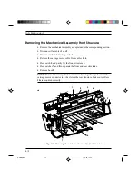
Removing the Mechanical Assembly Front Structure
•
Remove the mechanical assembly as explained in the corresponding section.
•
Disconnect flat cables 1 and 2.
•
Disconnect the ink discharge tube 3.
•
Release the carriage motor cable from cable clip 4.
•
Press catch 5 and partly lift the front structure 6.
•
Press catches 7 and 8 to separate the front and rear structures.
•
Remove bush 9.
NOTE: Before remounting the two structures back together again, insert the
carriage motor connector into the slot on the rear structure. Make sure rollers
10 are mounted correctly.
1
2
3
6
5 9
10
4
7
Fig. 8-9: Removing the mechanical assembly front structure
S-8BIS.PM5
11/7/94, 17:35
10
Содержание DECcolorwriter 120ic
Страница 58: ...3 21 Installation Fig 3 21 Fonts selector switches settings S 3 PM5 11 7 94 17 16 21 ...
Страница 59: ...3 22 Installation Fig 3 22 Character sets selector switches settings S 3 PM5 11 7 94 17 16 22 ...
Страница 60: ...3 23 Installation Fig 3 23 Character sets selector switches settings S 3 PM5 11 7 94 17 16 23 ...
Страница 69: ...5 3 Diagnostics and Tests Fig 5 1 Example of monochrome print test page 1 S 5 PM5 11 7 94 17 18 3 ...
Страница 78: ...7 3 Electrical Interconnections Fig 7 1 Main board S 7 PM5 3 14 97 3 38 PM 3 ...


